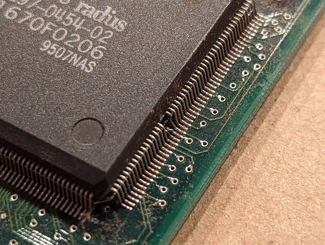
inside my Amiga 2000, i have a GVP processor card (with SCSI). but it's missing something -- can you see what?
it's missing the remaining 12MB of RAM! ๐ฑ
no problem, let's drop in a couple of spare sticks. but as you can see, it's neither 30 pin nor 72 pin. it is 64 pin nonstandard RAM. ๐คฆโโ๏ธ
correction: it's missing 8MB of ram. there is 4MB soldered on the board, and it has one slot populated.
i have a plan.
routing is going to be tricky. i think i'll need 4 layers.
not as bad as i thought. could still use a power and ground plane though.
ooooh sneaky! they hid bypass capacitors underneath the RAM chips! ๐
well that was easy. now i need to add bypass capacitors.
done! i put the new bypass caps in between the RAMs instead of underneath. also got rid of one bypass cap.
now with more 3d!
boards came in, and they fit the socket!
time to see if it works!
woah! it actually works! i can't believe it! ๐คฉ
i have a few more to build up. good thing i bought this solder stencil. anyone recommend a good brand of solder paste?
wish me luck! it's my first time with solder paste and reflow!
oh that was easier than I thought! time to pick and place.
nice! got them on there despite my shaking hands. if only i had one of those cute vacuum tools.
modded firmware, yeah!
starting the ramp. so exciting!
at the peak. heater lagged a tiny bit, hope it's ok.
ramp down! boy that fan is going.
*beep* and it's done. it's quite hot inside. i'll let it cool a bit before i open it up.
looks like 3 pins didn't get soldered. the paste didn't melt.
the rest looks ok though!
after touching up those solder joints, let's test it out! so far so good! ๐
yep, this works. ๐คฉ
got a little factory going on here, building and testing GVP SIMMs.
done with this batch! original one is on the right.
oh no!
hmm this vacuum tool only sucks for a few seconds before letting go. maybe there's a way to improve it.
wiped some chapstick off my lip and applied it to the rubber part. now it lasts for about 10 seconds. ๐๐
let's try to cobble something together
ok this seems to work pretty well.
yup. just need to find a foot switch.
green hose is vacuum, red hose is pressure supply to detach the part. there's a tee acting as exhaust, and the red hose goes through a needle valve to adjust the detach force.
too bad the pump sounds like an angry hornet. ๐
โข โข โข
Missing some Tweet in this thread? You can try to
force a refresh
i printed a new panel insert that has two BNC sockets on it (the original probes would have had captive cables)
the tricky part is that this oscilloscope has a 333K ohm input impedance instead of 1M like umm every other scope on the planet. fortunately someone designed a little conversion circuit...
in honor of Sim Wong Hoo, here's a quick historical review of the Sound Blaster! ๐งต
but first we have to go back to their first sound card, the Creative Music System from 1987. (image credit: Bratgoul on Wikipedia)
this card has some special "CMS-301" chips. if you peel back the sticker, they have had their top marks removed. they're actually SAA1099 synthesizer chips made by Philips. Creative wrote music composition software for musicians on the PC.