A long, deep, sigh as I pull out the parts for my next project. 


Trying to make long straight lines of LEDs.
Here lies madness.
Here lies madness.

🤔 A good start.

Now we install the 74LS245 transceivers and start wiring up the LEDs. Data bus D[7..0] first!

Annnnd address bus A[7..0]

24 LEDs wired up! A[15..0] and D[7..0]

Starting to ask myself if we *really* need to implement the whole 16 bit address space?


I think the technical term is "lit, af"

It would have been really nice if they had lined up the pinout on the two buses for the 74245.

I mean, I really hate the chips being offset by 100 thou on the front, but it makes the wiring so much easier on the back.

Bussssssssss

You really burn through a lot of 74LS245s playing with 8 bit processors. Three to buffer the addr/data bus LEDs, one for status LEDs, and three more to eventually buffer toggle switches into the addr/data buses.

Just showing off my status symbols!
*checks notes*
Errr... Scratch that. Status signals. I'm showing off status signals.
*checks notes*
Errr... Scratch that. Status signals. I'm showing off status signals.

I know this whole project would go faster if I just drew up the schematic in kicad and laid out a PCB, but that's not really the point.

Address bus done. We're getting closer... Then we can actually start working on the computer.

One handed smoke test! The three dark LEDs work too.

Smoke test with my @ZxSpectROM RC2014 Micro! Since I haven't implemented any of my changes vs that bus yet.
Yaaaaaasssssss!
The plan is to build a really really slow Z80 system so you can see each step, vs the vague bright or dim you get at 7MHz.

😁🤓😍 So much blinky is in my future!
Alright, well I've addressed that matter. On to the data bus and signals next.

This is a good sign. al.

Ignore the green data bus. Haven't wired those up yet so they're floating high.
Hard wired in no-ops
Hard wired in no-ops
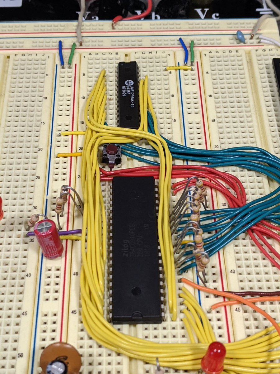
The awesome thing about the Z80 is that the max clock cycle time is infinite, so you can run it as slow as you want, but the *edges* of the clock need to still be pretty sharp.
I was violating that rise/fall time and making my Z80 very unhappy last night.
I was violating that rise/fall time and making my Z80 very unhappy last night.

So this easy and dirty clock circuit I made ABSOLUTELY DID NOT WORK.
All sorts of weird behavior. The program counter would suddenly load garbage, resets wouldn't work, etc etc.
All sorts of weird behavior. The program counter would suddenly load garbage, resets wouldn't work, etc etc.

For all of you enjoying this thread and all the memories it's bringing back, here's a friendly reminder of what I labeled the bags I've been collecting the parts for this project in.

This computer is looking awfully fetch at the moment.

Here you can see the expected operation of the Z80!
First some clock cycles in reset, then a few of the 4 cycle no-op fetch machine cycles! 😍
The bottom LEDs are M1, Read, Write, IOreq, MEMreq, so you can see fetch on the first cycle, then just MEMreq for refresh on the 3rd
First some clock cycles in reset, then a few of the 4 cycle no-op fetch machine cycles! 😍
The bottom LEDs are M1, Read, Write, IOreq, MEMreq, so you can see fetch on the first cycle, then just MEMreq for refresh on the 3rd
The part I don't get is that I thought these original NMOS Z80s were entirely static... 🤔
But they seem to melt down after a few seconds of no clock cycles...
But they seem to melt down after a few seconds of no clock cycles...
It works fine with the Z84C00 part I stole out of my RC2014 Micro, so I really don't get it... 😕
Sup?
I'll need this, eventually.
I'll need this, eventually.

Actual buttons for clock and reset, and they even work now.

First long-form video for this project! Single stepping through NO-OP and relative jump
Me, yesterday: "You know what would be really stupid at this point? Just adding dip switches to the data bus to be able to toggle in instructions during the fetch cycle."
Me, today: "lol. fuck."
Me, today: "lol. fuck."

Still really satisfying running NO-OPs at 60Hz with EMI from my body as a clock source.
Yeah. Togging in a program during each memory fetch cycle would definitely be stupid. Who would want to watch that?
R A M.

Achievement unlocked: we have made a LOOP! 😂
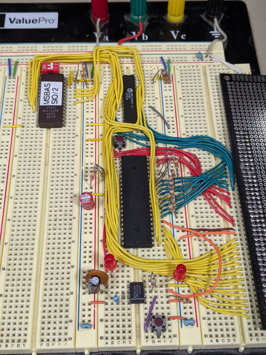
The nice thing about the 27C256 ROM and the 61256 RAM is that they have practically the same pinout!
Just need to jumper every pin on them together.
Just need to jumper every pin on them together.

I had previously gotten the feedback that there wasn't enough yellow on this project yet.
You happy now, @SamanthaSnyder? 🙃
You happy now, @SamanthaSnyder? 🙃
Time to start building some address decoding logic...

I think this OR gate is about as old as my parent's relationship.

/OE and /WE decoder: DONE!

It lives! Now we can... single step Microsoft BASIC...
the fact that it worked first shot after adding 50 wires since the last time I tested anything certainly says SOMETHING about me... not sure what...
the fact that it worked first shot after adding 50 wires since the last time I tested anything certainly says SOMETHING about me... not sure what...
The problem is that a few instructions in, we hit the next problem, which is that BASIC is trying to write to IO address 0x80... Where it expects to see an SIO, which we don't have on the board yet.

Woof. I "knew" that the SIO came in a 40 pin package, but I was kind of hoping I wouldn't need to wire up pretty much ALL the pins on it...
Maybe I'll just wait for those 68B50s I've got coming... 🤔
Maybe I'll just wait for those 68B50s I've got coming... 🤔

This looks like a much more reasonable wiring job.

Slowly working our way around.
I guess I need to burn a new EPROM at some point too...
I guess I need to burn a new EPROM at some point too...

The think I love about unix is that the tools are so simple and fundamental, that when I'm using a different size EPROM than the RC2014, I can be lazy and read its PROM, then use dd to cut out the part I need.

Burn, baby, burn.

The original MS BASIC ROM expects a 7.3MHz clock and runs the serial port at 115200 baud, so I THINK if I tune this 555 for 19.2kHz, the serial port will run at 300 baud... 🤔

I'm not entirely convinced this will or won't work...

Holy shit. 😂

This is going to get extremely tedious.
19kHz on the other hand is still too fast...
The cold start with 32k of RAM took several minutes.
Thanks to hardware flow control, we can really run this thing as slow as we want!
Copy-pasted the whole mandlebrot program into the terminal, and you can see BASIC pause at the end of each line to process it.
Buahahaha even listing the code is slow.
You know what's better than 19.2kHz?
75Hz...
75Hz...
I'm having a fun weekend. I hope you are also having a fun weekend.
🎊😂🎉🚨🚥💡⚡
Really makes you appreciate the difference between a cold start and a warm start when you're running at 75Hz.
That took way too God damn long. 😂
This makes this whole project extremely worth it! 😂
Das blinkenlight is pretty good.
Busy busy little computer! 😍
Running the RC2014 Mandlebrot program at 1.2kHz! 😂. github.com/RC2014Z80/RC20…
Today's YT update on the Breadboard computer. :)
Pull downs on the data bus helped quite a bit, since the data bus floats high otherwise during refresh cycles.
Next is blanking the address bus during refresh since thats just distracting.
Next is blanking the address bus during refresh since thats just distracting.