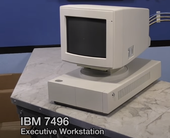
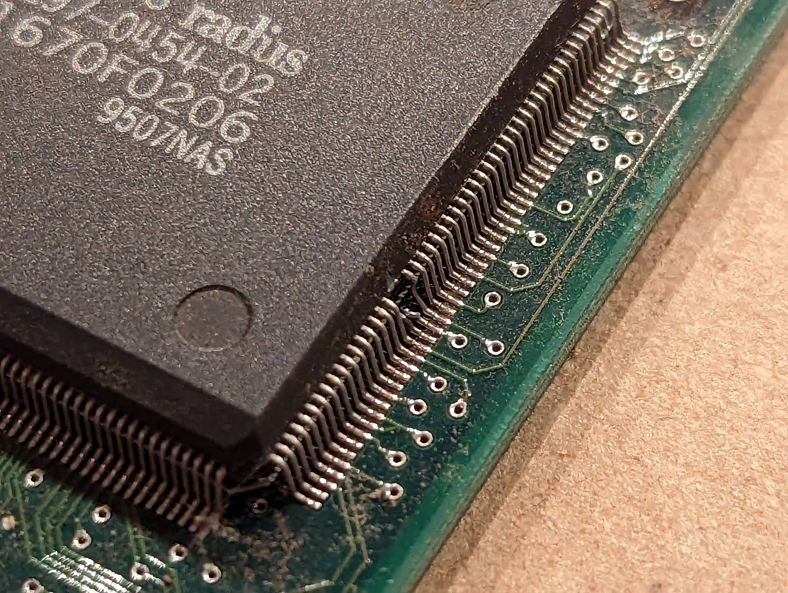
this video landed in my youtube feed this morning. give it a watch, but try not to get too angry; there are some good lessons to learn. 🧵
this is the IBM 7496 Executive Workstation. i've never heard about it before, and it's probably quite rare. but rare doesn't necessarily mean valuable. 

looking at the machine, it has some odd features. the tilted power jack is unusual; they must have run out of room in the case. 

the design language clearly follows the PS/2 line. there's a good chance it's based on a more common PS/2 machine. 

i think i have one or two of these kicking around. they're not necessarily valuable (unless you're a crazed IBM collector who wants a PS/2 with every last warranty card and plastic bag for every cable...) 

two beeps on POST for an IBM PS/2 is a display error. so something is wrong with the video on this machine. 

and that's because the motherboard IS for a PS/2 model 30. this is good, because info on that is a lot easier to find than on the 7496. 

incidentally, the sticker over the 3rd slot on the riser card is because the riser card is meant for a PS/2 model 30, which has room for another card! the part number is visible, and it is 61X8863. not hard to look that up. 

information on these connectors is in the PS/2 model 30 service manual. the second, longer connector is indeed for a hard drive. 

now we've gotten to the bad part. if you measure the resistance of a monitor AC line cord, you'll probably see a fairly low impedance. but why? 

typically there's a degaussing coil inside in series with a PTC device. when you switch it on, the coil activates and the PTC device heats up, increasing its internal resistance, and this deactivates the coil.
so this DC "dead short" is simply just the degaussing coil in the monitor.
not necessarily bad, if you're sure you got the pin connections right. i'd expect to see neutral, hot, and switched hot coming back from the monitor power switch. 

when you're messing with AC line voltage like this, it's also wise to check and double check everything with a multimeter. which pin goes to the neutral on the AC line cord? which pin goes to hot?
using a power strip with a built-in 10A breaker is a good idea, but often those circuit breakers don't work well and respond quite slowly.
a better idea is to wire up a simple circuit with a 100 watt light bulb in series with the AC line. if there is a dead short, the light bulb comes on. you don't want to use it for an extended period of time because it can be hard on switching power supplies.
i learned this lesson while repairing a 1000W audio amplifier's power supply. i replaced 6 giant switching FETs and then just plugged the thing in, without realizing that there was a shorted schottky diode in the output side. KERPOW! all 6 blew up and my ears rang all day!
okay no, this is just lazy. get the proper tool for the job. and if you have a dremel and a busted old screwdriver, you can make yourself a custom tool. don't use a dremel on a machine of which there are only 5 known to exist. 

if this were a more common machine then one trick to consider is to simply knock out the pin with a flat screwdriver. 

but nowadays you can find security torx drivers at hardware stores, so this whole mess was completely avoidable.
good thing it is a standard fuse. see how the wire inside is coiled around a fiberglass core? this increases the thermal mass and makes it take more time to blow. this is a slow-blow fuse. 

ok, off to the hardware store anyway. these fuses are *not* an exact match. the ones in the package are fast-blow fuses. 

ah ok now we can see the color code on the wires. there's an IEC standard for them:
blue: neutral
black: (not in the new IEC standard, but it meant hot in the old standard)
brown: hot
the black wire is probably the switched AC. shorting black to brown would likely have worked.
blue: neutral
black: (not in the new IEC standard, but it meant hot in the old standard)
brown: hot
the black wire is probably the switched AC. shorting black to brown would likely have worked.

remember the degaussing coil and the PTC? lots of inrush current there. also you have to charge up those big reservoir caps in the switching power supply.
yes, he just blew the fast-blow fuse. that's it. all it needs is the correct fuse.
yes, he just blew the fast-blow fuse. that's it. all it needs is the correct fuse.

ok, now we're going back to Computer Reset. this rings another warning bell in my head. "i did X to the thing, and it broke." that tells me NOT to do X to another example of the thing before i fully understand what went wrong. fortunately he's just powering the others on. 

ok second machine gives two beeps, so it also has the display error. my guess is bad video RAM, but it could be a number of different problems.
this could be bad video ram, but because some of the characters are shifted, i'm suspecting the MCGA gate array. 

ok now 8 Bit Guy is trying to boot DOS so that further diagnostics can be attempted. sounds reasonable. but what does this garbled screen mean? 

it's asking for the starter diskette! that's right, before you can start using a PS/2 model 30 (and likely this machine as well), you need to set up the contents of the CMOS RAM. and to do this, you need a starter diskette (the setup disk ought to work as well). 

he's guessing that the video problem is due to the video chip, which seems like a reasonable guess. every other line is shifted by 16 characters which sounds suspicious 


at first glance you might think it is a stuck address bit on the DRAM, but there are 160 bytes per line so you would see a staggered pattern, not something so neatly aligned.
more likely it has something to do with a counter in the 6845-compatible video controller inside the MCGA, but i know very little about MCGA so i could be wrong.
the 8 Bit Guy guesses that the floppy drive is bad, which is a pretty good guess. often they have leaking capacitors and won't work until those are replaced. but there's something else going on here. 

the BIOS will not boot off this disk because it wants a setup or starter diskette. how does it check for this? it looks for a flag in the first 512 bytes of the disk. no flag? no boot.
i also learned the hard way that if you take a setup disk and put it on a floppy drive in a modern computer, Windows will detect that the boot sector isn't quite right and then *silently change the flag back* at which point the PS/2 will no longer recognize it as a setup disk!
ok, trying an XT-IDE. like he said the BIOS will ignore the option ROM. anyway the actual IDE interface may conflict with the one on the motherboard. (which may not be IDE, but possible ESDI? i'm not really familiar with the 30) 

ok, trying a more modern floppy drive. cute adapter, i've designed one myself. the model 30 came with 720K drives, so it'd be wise to check what happens when you hook up a 1.44MB drive. 

naturally that didn't work either because the disk isn't a setup or starter disk.
swapping RAM is pointless because there's no RAM test failures on boot. 9-chip SIMM means that it has parity, so it would have thrown a POST error. 

not sure he's right about it being a prototype. i've seen hand written numbers on shipping hardware. it could be an early production run. perhaps they only ran off a pilot and then stopped? hard to say. 

i've seen and own some prototype IBM hardware, and typically there are stickers in various places identifying it. you'd easily be able to tell.
heh, in the B-roll showing the handwriting on the floppy cable, you can see the printed script for this segment of the video. 😃 

i'd also check the packing material to see if there were any paper labels that fell off.
OK time for a few lessons on working on old computers, particularly rare ones
✅use your eyes, inspect it carefully
✅do your research, look up part numbers, etc.
✅be patient, never be in a hurry
✅plan ahead, what might happen if you do something?
✅use your eyes, inspect it carefully
✅do your research, look up part numbers, etc.
✅be patient, never be in a hurry
✅plan ahead, what might happen if you do something?
✅check and recheck
✅no irreversible changes
✅use your brain. think logically.
✅no irreversible changes
✅use your brain. think logically.
my grandfather received one of these signs when he started working at IBM in 1954. i think it perfectly sums up what was missing from the video. 

@HakemonMike who pointed out that the Model 30, unlike the MCA PS/2s which i am most familiar with, does not require a setup disk to prepare it for the first boot, and the CMOS only stores the date and time. so i am wrong, and i am wrong because i didn't do enough research 😂
just to make sure it's clear, i'm not trying to come down too hard on the 8 Bit Guy. as vintage tech enthusiasts, we've all made mistakes and damaged old gear. i mean, i can think of quite a few dumb things that i've done over the years. the key is to learn from your mistakes.
and if you want to go galaxy brain, it also helps to learn from the mistakes of others
ooh i just thought of another good one
✅keep a detailed lab notebook--a debugging journal.
✅keep a detailed lab notebook--a debugging journal.
• • •
Missing some Tweet in this thread? You can try to
force a refresh


