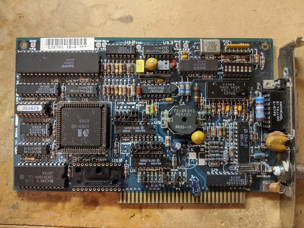
ok so what is the circuit? this is a 3Com Etherlink card from the late 1980s. you can see the neon lamp in the lower right. actually there's a bunch of other interesting things going on but first, the neon lamp! 

the circuit on the right side of the Ethernet card interfaces to the external AUI transceiver (the 15-pin D-sub) or a coaxial 10Base-2 network. the whole circuit is isolated by those two transformers, and i've put a red line so you can see no traces cross over. 


the neon lamp connects between the center conductor of the coaxial connector and the shield connection, and it is there to absorb electrical spikes. if a spike (induced by lightning or whatever) comes in on the coax, the neon lamp will light up and clamp it to 80V or so. 

it's a little like a neon-filled zener diode. but during normal operation, there's not enough voltage to exceed the breakdown of the neon gas inside, so the lamp remains dark.
nearby is another odd device. this is a ceramic capacitor but it has a slot cut in it. maybe i wanted to cut it in half but changed my mind? no, it came that way! 

this is a gap cap! the slot creates an air gap with a specific breakdown voltage, so it's like a capacitor with a built-in voltage limit. this discharges any static electricity buildup. 

the gap-cap goes between the outer shield of the 10Base-2 cable and the chassis ground of the Ethernet card, which achieves something very specific.
a capacitor here breaks the low-frequency and DC ground loop, while allowing high frequency (RF) current to pass through. since it is soldered directly to the chassis, most of the RF current flows here and not through the sensitive receiver circuit to the left.
if it was just an open circuit, the RF current would find an alternate path, probably through the receiver, adding a bunch of noise.
but if the shield of the coax cable was shorted to the chassis, then ground currents could flow, causing hum in audio circuits or allowing stray 60Hz currents to flow.
also on the card: a neat bypass capacitor which is just an axial glass package with a SMT capacitor inside it. 

there's a silkscreen label indicating that the Ethernet address is stored in this chip, an 82S123 from National Semiconductor. this is a 32-byte bipolar PROM which could store only about 1/2 this tweet's text. 

• • •
Missing some Tweet in this thread? You can try to
force a refresh


