here's a repair job from a friend. it's a rather rare IBM PC accelerator card. it's very dirty. let's dig in! 
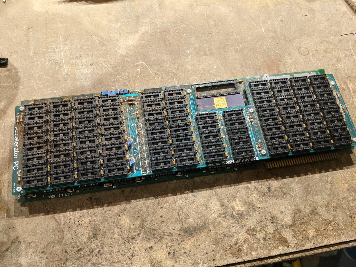
separating the two boards, you can see it is divided into a memory board and a CPU board.

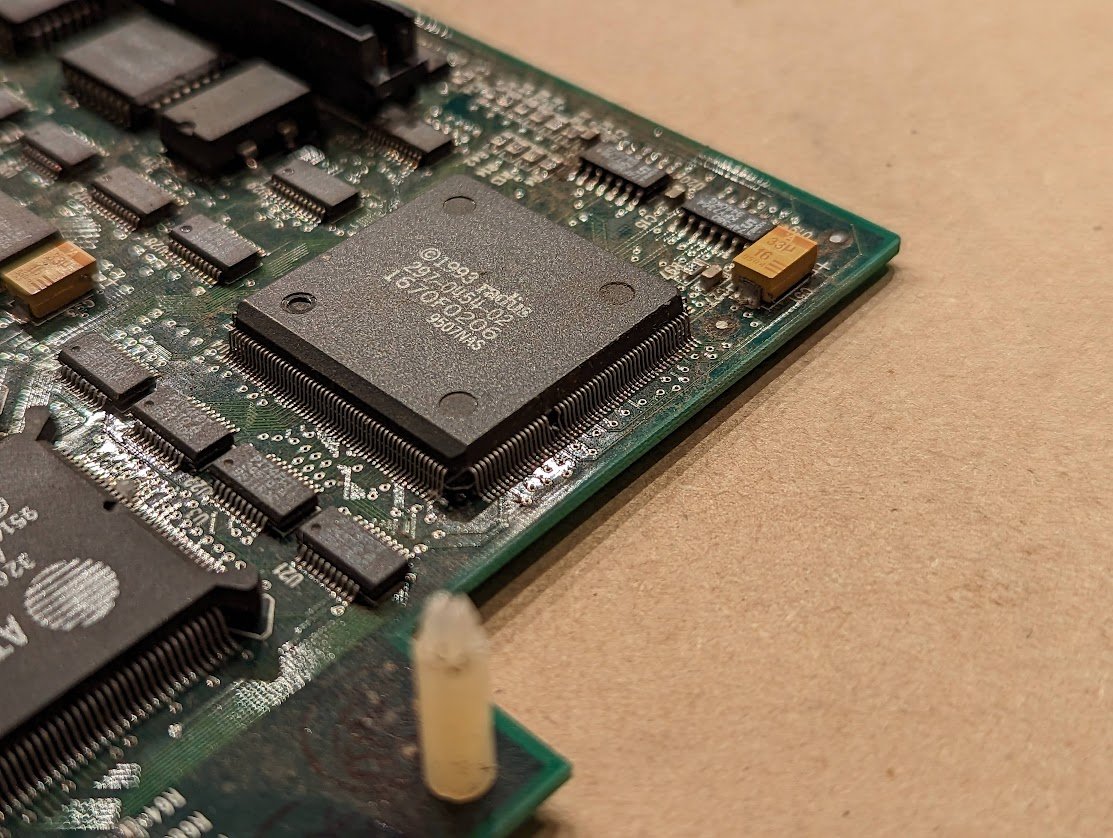
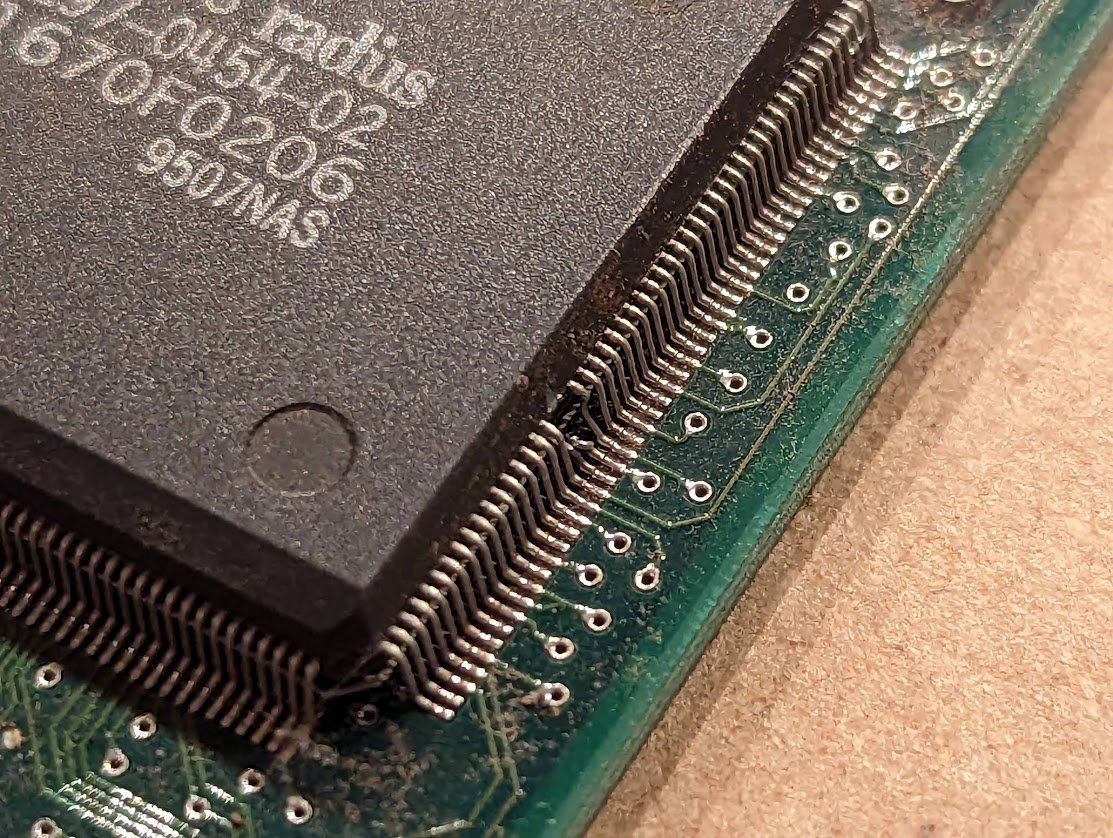
the upgrade CPU? an 8086. it's not a big upgrade from the 8088 in the PC, but presumably it is clocked twice as fast.

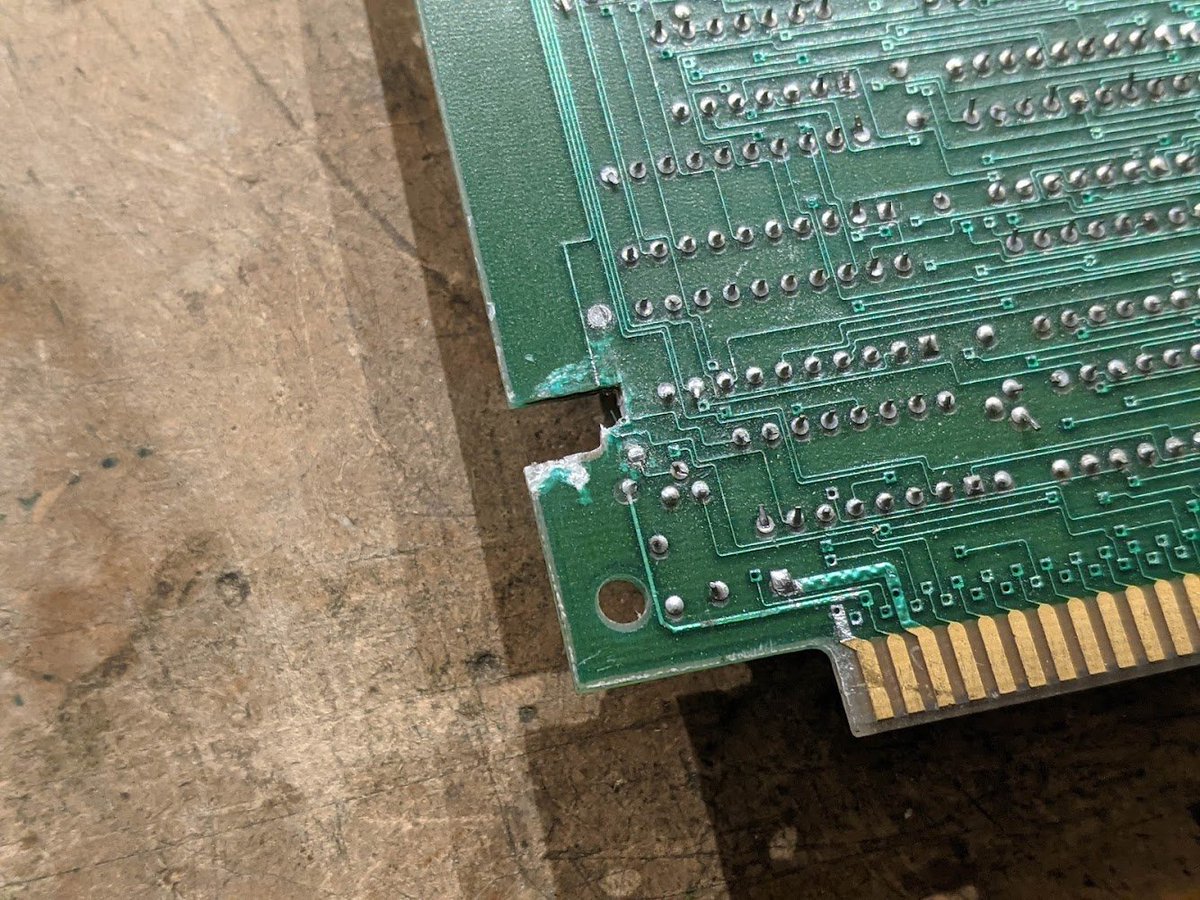
but here's the problem: it was found at an e-waste shop and they'd already torn off the bracket.

how would you fix this?

gluing and clamping. i've already removed some FR-4 material as well as part of the ground/power planes which were shorted out here. (4 layer board)

i need to add a little material here, and then i'll glue that in as well.
cut out a little chunk of fr4 from this scrap board

shaped to fit

now we wait for the glue to dry
hmm not half bad. I sanded it a little bit to smooth it out. doesn't have to be perfect.

took some before pics so I know where to run the traces.


soldered some fine wires to the existing traces.


not too shabby

elsewhere on the board, there's a bunch of sketchy stuff like this

this thing got mashed

sus

some people asked about how this card can take over the computer CPU on the motherboard. I suspect the 40 pin header on the upper right goes to a ribbon cable with a DIP plug, replacing the 8088.

so I think it's a straight-through ribbon cable. that's not hard to fabricate.

fabricated!

I'm expecting this to not work.

it didn't work. no beeps, the CRT didn't initialize. probably this isn't running code
I decided to test all the chips. they're socketed so it's easy. already found two bad ones!


all the other logic chips tested good. I dumped the two PALs (unprotected!) and now I'm trying to figure out how to dump this 82S129 PROM.

I'm not convinced this worked. I get 0xF for all memory locations except for 0x55, which reads as 0x0.

thinking about how to test the 8086, I was racking my brain trying to remember if I have an 8086 computer, but then

I remembered I have *the first* 8086 computer, Intel's SDK-86. and yes the chip works fine.

another thing to try is this WindsorPOST diagnostic ROM. you swap it in place of the regular PC BIOS chip, and it runs much more detailed tests with output to the video card right away. i doubt this will work either, but it's worth a shot.

i've completely reverse engineered the hardware for the WindsorPOST. it's got a really hilarious "copy protection" trick: it swaps the a0 and a1 pins on the ROM. one of these days i should use Ghidra to disassemble the firmware itself.
umm, i can't believe it, but IT FREAKIN WORKS

so the machine won't boot because it doesn't see any RAM! good ol' IBM BIOS just silently halts when it can't find RAM.

supposedly the card can use the system RAM, but i don't know if i've set these jumpers correctly. it's probably expecting to find RAM on the card itself.

OK i think i figured out what the jumpers mean. P means parity. 0, 1, 2, 3, 4 enable specific 128K banks of RAM, and F/S refers to the speed of the RAM chips (fast or slow).

i was a little worried that the empty sockets on the RAM board meant that it was missing some logic chips as well, but there are 90 sockets. for 4164 memory chips, that corresponds with 640K of RAM with parity. now i just need to figure out the socket->bank mapping.

i didn't noticed this before, but there are numbers at the top of each pair of columns. these must refer to the bank numbers!

and the identifiers P0, P1, etc refer to the pairs of chips required to provide parity for the banks that are used!

transferred some RAM from the motherboard. let's see if this works.

nope, still fails. that's odd

going to try probing the RAMs

probes connected

RAS=240ns, CAS=180ns. this is with the jumpers set to "F"
with the jumpers set to "S", i get RAS=384ns, CAS=232ns.
with the jumpers set to "S", i get RAS=384ns, CAS=232ns.

hmm, could be this card is picky about RAM.
stole some RAM off this Quadboard. the first bank is all 150ns, the rest is 200ns. now all 16 bits of RAM in bank 0 are the same manufacturer and speed. i wonder if this will work...

and the first 16K memory test passes now!

still, the diagnostic ROM hangs during the dynamic memory refresh test. i tried swapping in the standard BIOS chip and it still doesn't boot. so there's something else going on. maybe this card is only XT compatible? i don't know.
h/t @dschwarz who found this ad for the accelerator card.

i also found this blurb in "expanding and networking microcomputers." it seems that the memory board was an optional accessory. 🤔maybe there's a way to jumper the card so the high speed RAM is disabled.

sure enough, disabling all the RAM banks works. the board still hangs at the ram refresh test though.


so how to solve the ram refresh issue? i think i need to figure out where in the diagnostics it is hanging up. as an alternative, i could also try to figure out where it hangs up in the IBM BIOS.
here's the ROM dump of the WindsorPOST diagnostic. but something's not quite right


turns out the two lower address lines are swapped on that little adapter board.

well, here i am again, reverse engineering another BIOS 🤪

the CPU test is...lackluster. it runs 0 through all the registers, and then checks to make sure the result is 0. then there's a bunch of delay loops to make you think it's doing an *actually useful test* 😂

so it's freezing somewhere in this code. the last line highlights the text for the next test in progress, and it never makes it to that point. there are no loops. it just configures and enables the DMA+timer combo that starts the RAM refresh.

also amusing is this terrible interrupt controller test that just writes a bunch of sequential numbers to the interrupt mask register and reads them back. it does this 0x400 times and then calls it quits 😂

that memory refresh code is copied straight out of the IBM BIOS listing, but with the functionality checks removed. wild
check out this rework. they just drilled out the pin!

seems like all of my troubleshooting ends up here, with a logic analyzer snaking into the bowels of the thing

well, interesting. i want to explain this, but you would need to understand how the RAM refresh works on an original PC (5150)...

it starts with the timer chip, the 8253. channel 0 is for software use (timer tick), channel 2 is for the bleeps of the PC speaker, and channel 1 is for RAM refresh. there's a flip flop that it triggers, requesting DMA, and it gets cleared when the DMA is done.

you basically set up the timer to trigger every 15us or so, and that starts a DMA transfer. the DMA chip is set up to just increment the address over the full range of RAS (row addresses) and to just do a dummy read transfer. that refreshes the DRAM.

here the DACK0_BRD# signal disables the CAS pulse and asserts all the RAS lines so all the RAM banks refresh simultaneously.

the toughest part is this state machine that handles the bus mastering mode. circled in blue, the CPU must be in a certain state (passive) in order for DMA to take control of the bus.

the DMA controller has a whole handshake. DREQ (from the timer) starts the process. DMA asks for bus control with HRQ, the state machine waits until the CPU is passive, then it responds with HOLDA, and the DMA controller starts the transfer.

so here you can see DREQ0 is high, then CPU_STATE goes to 1 (passive), HOLDA goes high, and then the transfer happens (DMA_AEN#). the CPU READY pin goes low during this time, but what's with all those pulses? they look like glitches to me.

the 8284A clock generator chip takes the DMA_WAIT# and RDY#/WAIT signals, synchronizes them, and turns them into the READY output that goes to the CPU. when READY is low, it halts the processor.


so the extra glitches are probably not real, but the output high is around 2.1V which isn't great for the noise margin. notice the CPU_STATE doesn't change afterwards, so the 8086 on the accelerator card has locked up at this point.

it's time to probe the CPU card. probably the ready signal and the S0/S1/S2/LOCK state signals to start with.
and the 8086's READY line is going low and staying low, so it's not running code. this is odd because the READY line on the motherboard has gone high, so there must be some additional logic on the accelerator card.

this is weird, i am measuring 33 ohms to ground on the READY pin on the ribbon cable. this doesn't seem right. it also explains the low voltage on the READY pin on the 8088 socket on the motherboard.
and unfortunately this 33 ohms is below the threshold for my multimeter's continuity mode, so it's really hard to buzz out due to all the ground pin coming up as false positives. 😅
they did it on purpose. interesting.

time to start tracing the ready signal to see why it doesn't assert. the circled signal must go low for READY to assert. the second DFF synchronizes the signal to the clock.

uh oh. the logic expands into 4 input signals and a signal coming from a PAL.

this is starting to get complicated

ok usually when i work on these things, the signals start collapsing down into state machines, decoders, etc. but now i've got 14 (!) signals feeding in, not including the PAL.

pulling this one thread seems to be unraveling the entire sweater. think i'll take a break for now.
short break; i'm back! and figured out the tiny ROM. it's used as an address decoder.


the tool of choice. not shown: a multimeter set to continuity mode

sus

unbelievably, all those traces are fine. 🤔
took me all day, but i finished up with the PCB reverse engineering. i need to organize it a bit and start to figure out how the READY circuit is supposed to work.

using a process of elimination, i figured out that the signal that's having issues passes through U1, this PAL. so now i need to figure out how to get from the bitstream to the gates. 🤔

there's a program called JED2AHDL, but it looks like it'll take some work to get it going.
i may be overthinking this


not complicated


PAL equation backed out by hand. looks like this mostly comes from a cycle counter.


now back to the real hardware. no pulses on U3 pin 5 appear after the DMA operation. this is driven by the PAL. i'll just keep working my way back up the line...


the PAL clock goes away. looks like the PAL is behaving itself, but the clock disappears and doesn't come back.

pin 12 of U30 goes low and stays low. that's not right.


it's stuck low because this flip flop never receives a clock pulse after a certain amount of time.


huh, weird, there's a fat pulse on one of the NOR gate inputs, then they both stay high and that's it

flip flop U29 is getting stuck low. to get unstuck, the output of U30B must go from low to high. this is triggered when the ISA bus tries to write to RAM (in this case, the DMA controller).


it's gotta be this flip flop. it's supposed to reset when AEN goes low.

getting ready to connect the probes to U28, and look! the problem! 🤦♂️

pin 8 is just chillin there outside the socket
oh yeah it passes the test now

boots DOS!

all that's left is to try out the memory daughterboard. but i have a bunch of memory chips to install in it first. gotta populate the rest of these sockets.

benchmarks! it's faster.

here's how this similar system compares with the 5150.

anyway, if you're interested in this card, someone is selling one on ebay right now. ebay.com/itm/Accelerato…
as for this card, it's going back to its owner, who i am sure will be delighted to have a working card.
i probably ought to release the schematics that i have. maybe the PAL dumps too. it's no clone, but it'll be useful for repair.
• • •
Missing some Tweet in this thread? You can try to
force a refresh