today's project is to fix this old Seagate ST-412 hard drive. 10MB, full height, and really loud! 

here's a problem: the positioner stepper seems to move around randomly on power up. it's supposed to wait until the rpm goes nominal before moving. could be an issue with one of the motor phases.
looks like the stepper is controlled from an MCU. but there's some electronics in between i should check.

during a power-on, two of the phase signals don't look right
i've find an open-collector inverter that seems to be dead, pulling all outputs low regardless of the inputs.

desoldered. now I can test it.

it seems to work, which is really weird.

the OC outputs are going into transistor bases, so i was confusing 0.7 volts as "low" when it is really "open"
if anyone wants to follow along, i'm using this manual: wang2200.org/docs/external/…
unfortunately it doesn't match my board p/n, which is 20221. the manual covers 20096 and 20110.
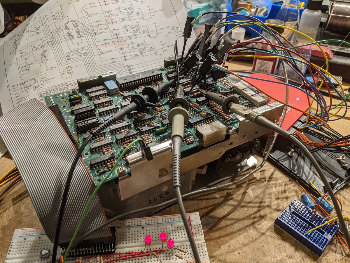
logic analyzer time.

looks like the MCU is toggling some GPIO pins during startup. this only happens when the motor is connected. maybe motor switching noise is confusing it? starting to suspect power integrity problems.

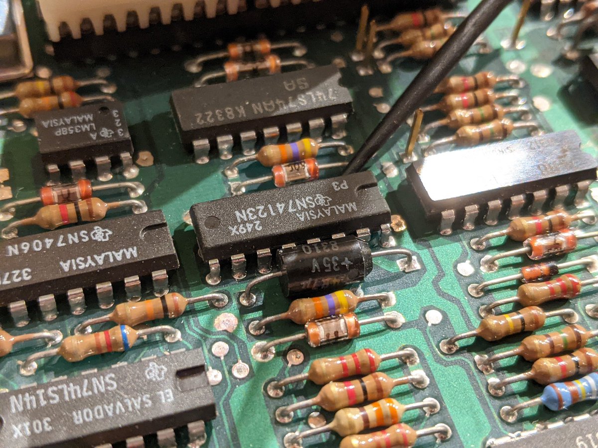
oh and the reset# line is toggling, and shouldn't. there's a 74123 one-shot that's toggling the line with no input trigger pulse!
the 74123 currently under suspicion. and yes that is a tantalum timing cap. 🤔
tantalum has capacitance. maybe there's a leakage current?

leakage is fine too. hmm.

hmm this capacitor on the 12V rail isn't doing well. 12 ohm ESR is really bad

the 74123 circuit, for those who want to follow along. it just generates the reset pulse.

-DCUSF comes from this circuit that monitors the input supply voltage. one guess is that the 12V rail is super flaky and goes above and below the threshold when the motor is spinning up, causing the reset line to spaz out

swapping out some suspicious capacitors. ESR was getting pretty high.

there was a lot of ripple on the 12V rail during the motor startup. part of it was the bad caps, part of it is the bench supply i'm using. this was triggering the supply monitoring circuit, which is working fine. there's still another problem though.
so here's where we're at: the DCUSF signal (from the supply voltage monitoring circuit) is good. the RST# pulse generated by the '123 one-shot has a pulse right at the beginning, which doesn't seem right.

looks like the pulse occurs during the VDD ramp-up, when it hits 3.3V.

I think this is a red herring, and is an artifact caused by my bench supply. it doesn't occur with a regular PC power supply.
here's the remaining issue: I can't seek to track 0; it just bounces back!
in this video, I start out at track 0, seek to track 1, and then try to seek back to track 0. notice that it jumps to like track 4 or something instead of going back to track 0?
I polished up these silver-plated BNC connectors. why? well

to make this adapter that lets me use 10x probes with my Saleae logic analog channels.

the Saleae input impedance is 2M ohms so I have to parallel it up with a 2M resistor in order for the probe to work right

and I need this to check the stepper motor's commutation waveforms.

they...sort of seem ok? i need to look at the digital driving waveforms as well.

ugh, the schematic doesn't quite match

new symptom: it can now go to track zero but it refuses to seek more than 4 tracks down. this is starting to smell like an MCU issue.
the track 0 indicator is asserting like every 4 tracks. clearly it's losing track...
🤦♂️

so that connector was for the LED+photodiode used to sense track 0. once i reconnected it, we're back to the same old symptoms as before.
from what i can see, the electronics driving the stepper motor seem to be OK, but the motor behaves very oddly when it's close to track 0. the steps are of uneven size, and i can feel some mechanical resistance. perhaps it's been a mechanical issue this whole time.
and then there were two!

trying a brain transplant

yup, this must be a mechanical problem
welp, there goes the warranty

hmm

head crash, perhaps? or maybe the head got stuck here for a while.

ok so the track zero sensor hasn't been hit but the head assembly has hit this hard stop.

the hard stop is set from the outside.

see how the glue is cracked? someone's messed with it. 🤔

the adjustments for the track zero stop on the stepper motor appear untouched.

I've tapped the differential signal coming off the read amp. by looking at the amplitude I can see how far out of alignment it is.


yeah bearings in the stepper are shot 🙁
on the other drive, the track zero sensor seems to be positioned differently--notice how the lever is further out? 🤔

swapped the track 0 sensor and the darn thing steps correctly now!
took the old sensor and filed down part of the plastic. it's really close, so I'm not sure why it wasn't working right.

forgot to mention that i also added some lubrication to the stepper motor shaft, although i doubt that did much now that i think about where the bearings are, lol
think it's time to pick out an MFM controller card and try out this drive

jury rigged in my XT.

it's detected!

won't boot and gives me this error when I try to fdisk.

let's try a low level format. nice little secret command that you enter from DEBUG, lol.

good so far

argh

i think i'll need to hook it up to a logic analyzer and look at the raw sector data, sort of like how i did it for this other hard drive:
https://twitter.com/TubeTimeUS/status/1383198299922919426
looks like there is indeed data on track 0. i think it's head 3.

histogram looks great. we have edges at 100, 150, and 200ns.

i'm assuming there's an issue with the controller, so i switched over to a Xebec controller. this one you have to low-level format using debug by writing a short program that makes int13 calls!

fdisk sees the drive! it allowed me to partition it! it's formatting right now. 😃
oh yeah, it works! now i'm curious to figure out why the DTC controller wasn't working. (i borrowed the Xebec controller from my 3270 PC.)
the two controllers likely have a different, incompatible low-level format. so this drive, formatted in the Xebec, won't read with the DTC controller.
anyway, I'm looking at the other drive again and it's now showing the same weirdness with the track 0 sensor. it allows the stepper to go too far. there's no data in this area--the signal from the preamp is quiet.


I can get it to work by wedging some folded paper in this spot. I think the plastic of the sensor housing deforms with age and drops away from the correct location.

as I push on it you can see the track 0 signal dropping in and out.
so here are some useful tricks for the ST-412: you can probe the raw signal from the head at this test point (near the NE592).


having a breakout board is useful for controlling the drive. basically it holds the drive select line low and lets you see the track 0, drive ready, and other status signals. you can also step the heads in and out.

when you turn on the drive, step around the tracks a bit, and if you don't see any data on the first 4-7 tracks or so, then you know that there's a problem with the track 0 sensor.
go to the first track that has data on it, and then wedge some paper into the sensor in the spot i showed previously. when the breakout board's track 0 indicator LED comes on, then you know you have it. you can step around a bit to make sure it is not marginal.
i bet this is a pretty common failure mode for this drive. the plastic ages, and then due to the screw pressure it bows and bends downwards, pulling away from the lever, shifting the drive's idea of track 0 pretty significantly.

another fun trick: when on a track and while viewing the preamplifier signal on an oscilloscope, you can gently push on the stepper lever with your finger and watch the signal amplitude increase and decrease. this lets you check the drive's track alignment.
and then there were three!

• • •
Missing some Tweet in this thread? You can try to
force a refresh