i'm working on a Micro Channel POST (power on self test) card. the PS/2 BIOS writes checkpoint values to an IO port, and this card will be able to read and display those values. i'll keep this thread up to date as i design it. 

yesterday on the live stream i designed the address decoder. i started to design the LED display but hit a snag when i realized that the 4511 chips only do BCD to decimal and can't handle A-F.

there aren't any readily-available chips that do binary to 7-segment hexadecimal. alternatives include
❓PALs/GALs
❓a microcontroller
❓a CPLD
❓a pile of TTL
❓a ROM chip
❓PALs/GALs
❓a microcontroller
❓a CPLD
❓a pile of TTL
❓a ROM chip
each has drawbacks. i am hesitant to use a programmable device on the board, or at least one that requires expensive programming hardware. there are also the ongoing supply chain issues.
using a microcontroller might work--there are still some ATmega devices available in DIP. but i would also need two additional 8-bit latch chips since the Micro Channel bus is very fast. the ATmega would just drive the LED display.

it could work something like this.
https://twitter.com/RueNahcMohr/status/1480002733826478080
but how about a GAL? a 16V8 could easily decode binary to 7-segment hex. there are a couple of approaches i've thought of

one is to have the 16V8 decode the full 8-bit value as it is written, and then store the segment data into four 8-bit latches. that is 5 chips total.
(this board will support two 8-bit number displays, aka 4 digits)
another approach is to have two 8-bit latches to store the values, and then have two GALs to decode an 8-bit number into a multiplexed dual 7-segment display. this is 4 chips plus an external oscillator (or bus clk divided down by a 5th chip)
or each display digit could have its own GAL16V8, with 7 outputs driving the segments, 4 inputs from the bus, and the clock input would drive a built in latch. this is pretty much a 4511 with hexadecimal capability, but with more pins.
and yes there are a bunch of other ways to do this, like with a TIL311 display that has a built-in decoder. they're a bit more expensive and harder to get, however.

one advantage of using a 16V8 is that they're not hard to find, there's tons of stock in surplus, they're cheap, and can be programmed with a very cheap TL866.
a disadvantage is that i hate WinCupl. 😐

to use the built-in latches in the 16V8, the magic incantation is to drive the '.d' extension. this is the data input of the pin latch. did i mention i hate WinCupl?
quick test bench and this looks good.

now to try it out irl. this is my TL866A. true story: i won it at a holiday gift exchange a few years ago, but i had to "steal" it from someone else. hehe

and here it is, working. the tact switch goes to the clock input to trigger the latch.

the 16V8 can drive the LEDs directly, but only with a logic '0' output since it can sink a lot more current than it can source. i just use a common anode display and drive the cathodes.

oh yeah some folks are saying "galasm" instead of WinCupl. here's why i will never use galasm.

so if i design something using galasm, then that design can never be a commercial product, even if i am not the one who manufactures it. oh well.
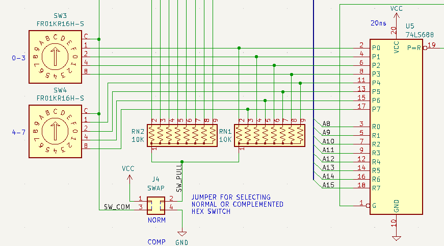
so here's the (mostly) finished schematic for one of the two hex displays. dial in the address and it will display whatever gets written there.

i'm starting to get other ideas too. maybe adding an activity LED would be nice. something that would flash whenever the port gets written to (or even read from?)
now for the info panel. that's this LED display. it was only present on the PS/2 Model 95, but the code to support it is present in the BIOS of other systems, such as the Model 77 that i fixed for Curious Marc.

fortunately it has already been well studied, and others have figured out the schematic.
ardent-tool.com/85_95/Op_Panel…
ardent-tool.com/85_95/Op_Panel…
the display is actually two HDLG-2416 4-character displays right next to each other.

you can still get them but Digi-Key wants $40 each!
digikey.com/en/products/de…
digikey.com/en/products/de…
hmm, perhaps this should be an optional feature lol
going to use a GAL to decode the address since it is always at 0108-010F. unfortunately it looks like i need something bigger than a 16V8 since i need to latch the A0 and A1 lines. or maybe a separate latch chip.

A 22V10 or a 20V8 would work. or i could put in a 74XX174 which has 6 D flip flops. i could use two of them for the dual hex displays.

it might look like this. (there are two sets of displays so you could use either the HDLx-1414 or the HDLx-2416)

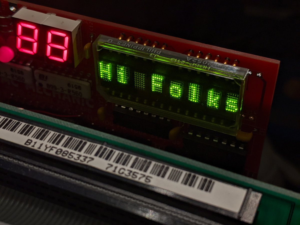
or maybe i could add support for the HDSP-2113. 8 digits and Digi-Key wants $55 each, so that's cheaper than two of the 4 digit ones.

only problem is that the HDSP-2113 address lines are set up such that the leftmost character location is at 000. the other displays put 00 at the rightmost character location, like a calculator i guess.


no problem though, i can switch to using a 74xx175 which has 4 flip flops and outputs the normal and inverted signals. the latched and inverted A2 line can come from the spare output on the 16V8. the remaining two latches can be used for the dual hex displays!

today i ended up redoing this part of the circuit using a GAL20V8 (or 22V10).

added a voltage monitoring circuit. the LED won't turn on until the voltage exceeds a particular threshold.

now for the boring part.

footprint time! looks like kicad 6 has a new color scheme. not sure how i feel about it.

the next step is parts placement. everything has to go in the right spot.

here's the first cut at a parts placement. the mess on the left are three options for the 8-digit LED status display. they overlap since only one can be used at a time.

i'm not entirely happy with this design. do i really need two hex displays to examine two I/O ports at once? do i really need the fancy analog voltage monitor?
there, this is a bit more compact. also a lot cheaper to order from the usual board shops.

the layout is a bit tight for 2 layers.
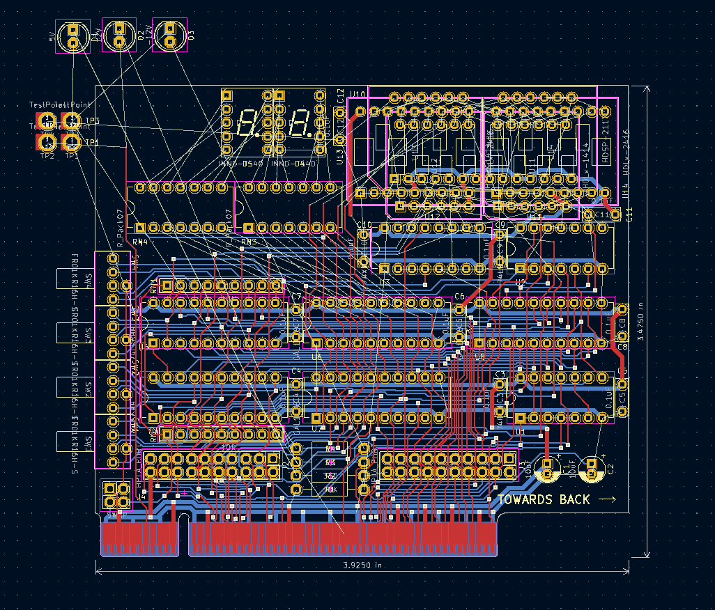
always takes a bit longer for layout than you plan for... still needs a bunch of cleanup, then silkscreen

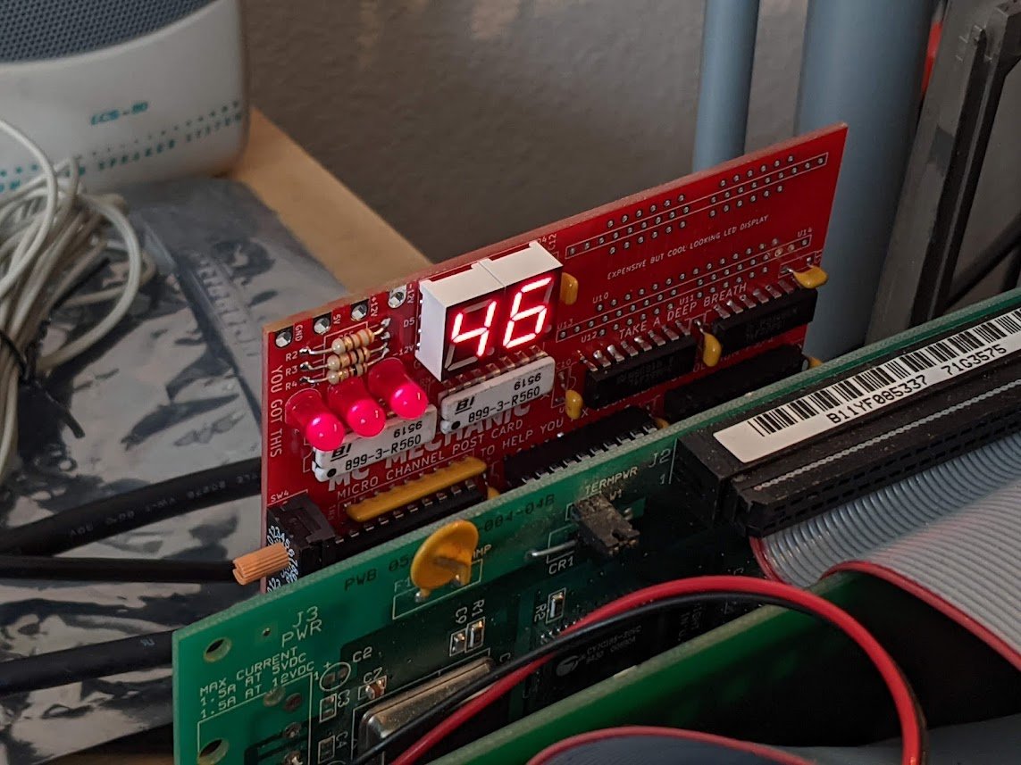
oh look, a board came in!

got it soldered up, too. i'm skipping on the 8-digit display for now, at least until i get the 2-digit display working.

it passes the smoke test!

it's got some weird issues in the actual PS/2 machine though. basically the display updates constantly when it shouldn't be updating.
looks like i'm going to need the logic analyzer connections. oh well.

so the Saleae is showing me that the address comparators are randomly tripping when they shouldn't be. in other words, the address doesn't match but the output asserts anyway.
ahh, the voltage on one of the comparator inputs is around 1.5V! this is because the pulldown resistors are 10K but the input current required to drive VIL is up to 600uA! gotta love 74F series logic.

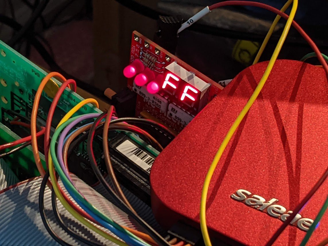
well, that seemed to fix the problem. but now there is a new one--a glitch on the select output causing the LED driver to double-latch the data byte. unfortunately the second runt pulse always latches FF.

swapped an OR gate with an AND gate and added a bodge wire. let's see if this works.

oh yeah! it works now.
let's see if this 8-digit LED display works.

nice! it works but I had to swap out a chip. so now the POST display doesn't work. just have to figure out how to have them both work at once.
here's the glitch that was causing the issue. it's only 18ns wide. hmm.


let's add a little RC delay to CMD. this is actually sorta terrible since this is straight off the bus, no buffer.

no more glitch!

oh it works in my model 95 as well! the display here just mirrors the one on the front panel.

and it works in @curious_marc's PS/2 model 77! this machine doesn't come with an 8-character status display but the code to support it still exists in the BIOS.

• • •
Missing some Tweet in this thread? You can try to
force a refresh