this is the story of a weird old ROM chip -- with a mystery that i'm going to try to solve. 🧵 

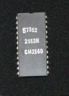
here is what i know: it was manufactured by Signetics in 1974, so it's about 48 years old.
it is very similar to the ROM chip that was used in the Apple 1, but not identical. something is different.

the Apple 1 used a ROM with the same base part number (2513N) but with a CM2140 suffix.
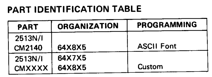
from the datasheet, CM2140 means that the ROM contains an ASCII font. other part number suffixes are just labeled "custom" with no explanation.
mine is marked "CM5440." but what does it contain?

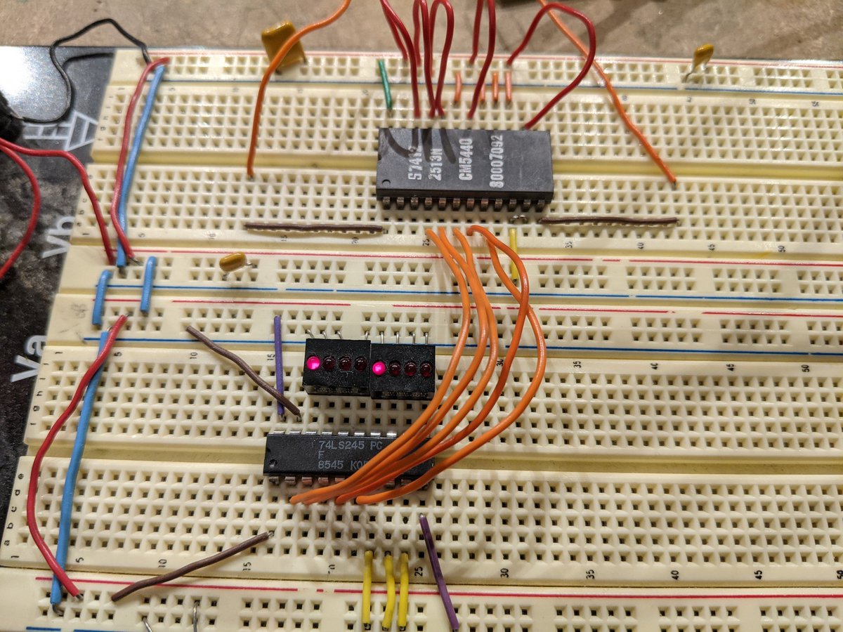
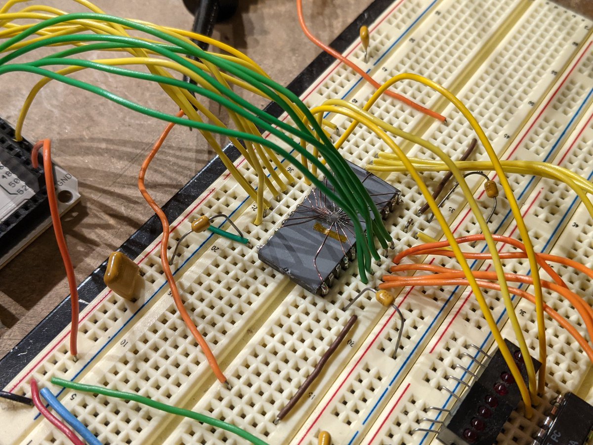
to find out, i'll need to build up a breadboard circuit to read it back.
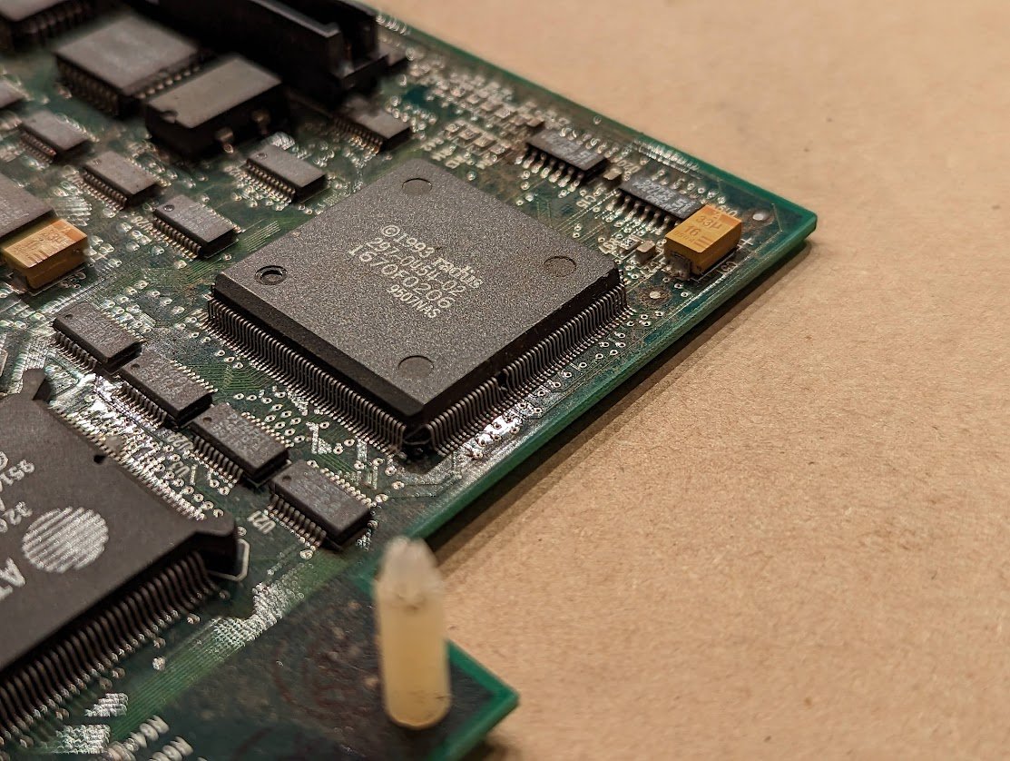
the chip has VCC, VDD, and VGG! yes, three power supply pins.

5V, -5V, and -12V (!)
also notice that it has 5 output data bits, not 8, since it is designed to store a 5x7 character, not byte-based data.
just need to wire up the address lines.

first tantalizing signs of data
first character. maybe an underlined carat? _^

it's hard to get a good read. here's one that looks OK.

amazingly enough, i just can't make heads or tails of this. perhaps the address lines got swizzled? (gridlines are at 8 line intervals)

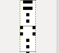
got a good read this time, my data setup time wasn't right. still though this appears to be incomplete. maybe this is half a character, and these are symbols or something?

it could be a custom ROM. you'd send Signetics a deck of punch cards with the data for the ROM.


this would be the contents of the ROM if it was their off the shelf version

ooh they have a table of some of the other character sets available!
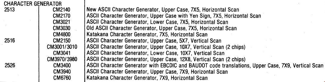
(click the previous image to see the CMxxxx part numbers)
well, i'm stumped. if anyone wants to dig around in the raw data, i've uploaded it here: tubetime.us/wp-content/upl…
(i was hoping it would be some cool alternate character set, but that doesn't appear to be the case)
(i was hoping it would be some cool alternate character set, but that doesn't appear to be the case)
wow, dumb mistake. pin 13 is a no connect, I need to shift these 3 address lines up by one pin. 🤦♂️

well this looks strange.

looks like pin 15 (A2) and pin 16 (A3) are shorted together. in the chip. 😭
should i attempt to clear the short?
hmm, i set up a power supply with a current limit. i went up to 350mA and it will not clear. i'm a little afraid of burning up a bond wire.
looks like the short is about 0.33 ohms.
at 1A, it's still not clearing. that's a lot for a bond wire, so perhaps this is a lead frame short. hmmm
it cleared at about 3A. unfortunately the A2 line no longer shows a diode to VCC, so i think the connection is broken.
and a readback confirms it. A1=lsb, so that's toggling, but it is repeating pairs of lines, so A2 is dead.
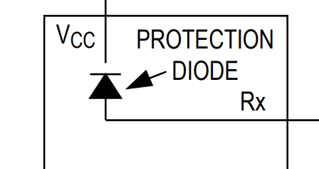
"shows a diode to vcc"
there's usually an ESD diode clamp (or parasitic diode) from each pin to vcc. if the bond wire (or the chip metallization) blows, then i won't be able to detect that diode anymore.
there's usually an ESD diode clamp (or parasitic diode) from each pin to vcc. if the bond wire (or the chip metallization) blows, then i won't be able to detect that diode anymore.
i've got another trick up my sleeve, but it takes more time so i think i'll save it for tomorrow.
let's pretend it's tomorrow. anyway I really want to know what this contains. time for more drastic methods.

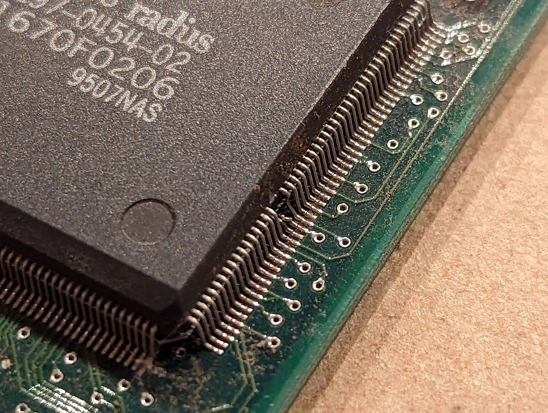
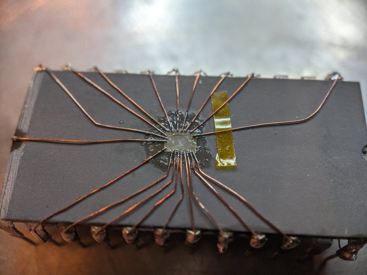
bond wires are visible.

here's a first look at the die. there's still encapsulant on top but I put a little isopropyl alcohol on top which makes it go transparent. can you see the shorted address lines?

I've got some ideas...

got the bond diagram figured out. VCC is what's known as a "down bond" because it is connected to the metal paddle underneath the chip, and is electrically connected to the die substrate.

makes sense because this is PMOS. NMOS would have a GND down bond.
cleared the short with a fresh exacto blade.

there's no way this will work. yeah I've soldered new "bond wires" to the remaining bits of the old, gold bond wires on this chip.
this probably won't work but it is worth a shot.
so close! the chip powers up and i can see some valid data but there's also some garbage as well. perhaps the chip is light sensitive? or maybe i have a broken wire.

this is about as good as i can get it. there's an all capitals alphabet in there, but that's some pretty seriously corrupted data. maybe i overheated it while soldering? maybe damage from when i was forcing current into the shorted pins? who knows.

my guess is that this chip NEVER worked and was a factory reject.
the plot thickens

address line A7 was shorted to VCC. I tried dumping it without that line connected, and I get garbage.

another one of them has a stuck output. and the stuck output doesn't matter because the contents also seems to be garbage.

and the last one has no stuck inputs or outputs...BUT the output is still garbage. i guess i should check to see if it's the same garbage as the others.
here's a compatible part. let's see if it works, just so I can verify my setup.

ahh, this one works! looks like i reversed the bit order though.

the chip with the bad data line and the chip with the "garbage" contain exactly the same garbage. that's really weird. i'm getting a funny feeling that the scan lines for each character are out of order.

it's more than just lines out of order. btw it looks like the ROM contains lowercase letters. see how they match up 1:1?

perhaps the semiconductor masks were out of alignment and this was a whole bad run of chips? I don't understand how else the ROMs I can read are all exactly the same garbage.
still can't believe this worked!

finished decapping it. (light sanding with IPA, then switched to gentle scrubbing with a qtip and acetone)

looks like it is possible to read out this ROM optically.

you can see part of the address decoder here, highlighted in red: a classic binary pattern.

here's a better photo under a better microscope!

oh yeah this is way better.

five bits of the address come up into this block in the middle, which buffers them and generates an inverted version of each bit. the 10 outputs go into a 32-output decoder, above. this drives 32 select lines into the ROM array on the left.

the bottom 8 rows going through the array are decoded from the 3 least significant address bits. if you stare, you can see the binary pattern that selects a single set of columns based on all the address bits.

a single output bit gets selected from one of 16 possible columns. there are 5 output bits, so there are 80 columns total.

these are the address inputs. the gold dot is the remains of the wire going to the pin. the squiggly line is a series resistor, and the fork-like thing is an ESD protection diode.

anyway this is a diffusion ROM. you can faintly see the bits, which are the little orange squares (transistors) underneath the metal layer. if a transistor exists in a bit position, it shorts out the column output if its row input is selected.

I'm going to need more images so I can optically dump the ROM.
oh yeah this imagery is way better. the orange things are transistors (circled). the vertical blue lines are just supply rails. in between are the 8 columns, which are outputs. the green lines are the 32 row inputs, one selected at a time.

earlier today, @kenshirriff and i were working on this ROM, and we decided to race each other--he would take a bunch of photos of the die, stitch them together, and run them through software to extract the bits, and i would do it manually under the microscope.
here is the resulting data. this is mapped 1:1 as it is laid out in the ROM on the chip itself. oh yeah, and guess who won the race?
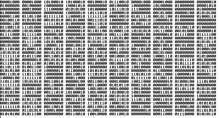
the stitching software was troublesome, and i ended up winning the race just doing it by hand. 😋
i wrote a shitty python program to convert the raw ROM data back into a correctly-mapped binary. and here's what i get. look familiar?

yup, it's the same garbage. (the order of characters is different because i didn't decode the 32 row address lines correctly)
so here's what we know:
1) the chips contain the same data
2) one chip had a bad output. another chip had shorted address lines.
3) the data is real and matches what i see optically
1) the chips contain the same data
2) one chip had a bad output. another chip had shorted address lines.
3) the data is real and matches what i see optically
so what is going on? i don't think the data is garbage. it's possible someone at Signetics dropped the punch card deck from the customer and put it back together all out of order, BUT it is more likely that the address lines have been swizzled in some way.
• • •
Missing some Tweet in this thread? You can try to
force a refresh