
oh hai! it's a new arrival: an HP 150. it's a semi-compatible PC from 1983. it runs MS-DOS. 
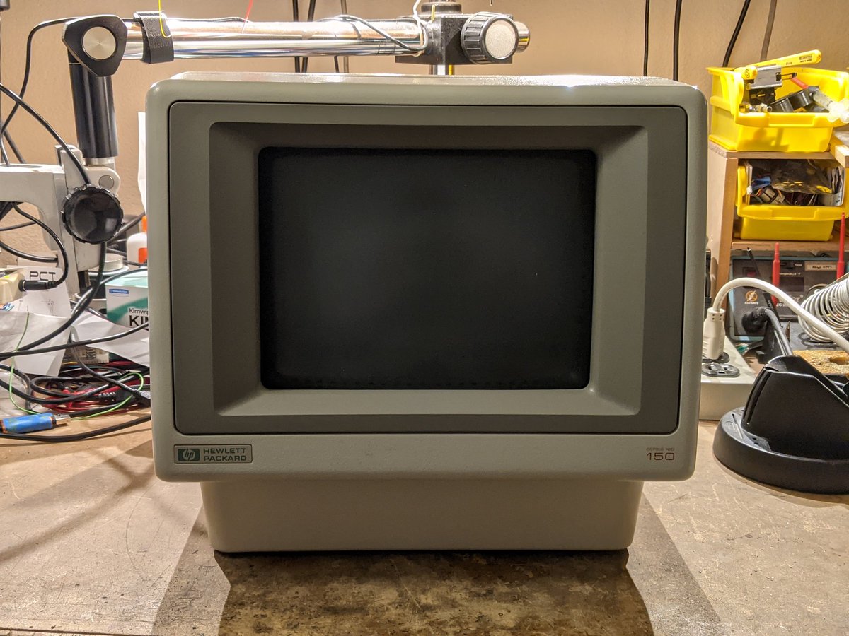
there's even a built-in thermal printer in the top!

on the back it has two serial ports, the keyboard port, and an HPIB port. there are also two expansion slots on the bottom.

but what about disk drives? oh, those are external, and connected to the 150 using HPIB.

such as this 9133 from yesterday's thread. it has a single floppy drive and a 15MB hard drive.

hmm, blank screen when I switch it on.

let's look at the diagnostic LEDs on the back.
what does it mean? all of them flash meaning that the power-on reset works. then it does half a Larson scanner so we know the CPU and ROM are working. after that come the error codes.
each error code is 16 bits long. the 4 rightmost LEDs display a binary nybble, and the 2 leftmost LEDs indicate which nybble in the word it is displaying.
so
00 0011 = 3
01 0011 = 3
10 0010 = 2
11 0000 = 0
-> the error code is 3320.
00 0011 = 3
01 0011 = 3
10 0010 = 2
11 0000 = 0
-> the error code is 3320.
there's a service manual that describes the error codes. hpmuseum.net/exhibit.php?hw…
in this case, it seems like a RAM failure. presumably the '20' code at the end identifies which bit failed.

so i got four error codes:
3320 - user memory bank 3 marching 1s failure
8210 - non-socketed component failure (hmm)
9120 - keyboard failure (nothing plugged in lol)
2320 - user memory bank 3 failed refresh
3320 - user memory bank 3 marching 1s failure
8210 - non-socketed component failure (hmm)
9120 - keyboard failure (nothing plugged in lol)
2320 - user memory bank 3 failed refresh
welp, gotta take it apart. there are two cards plugged in. the upper one is video, the lower one is the CPU with a memory daughterboard and one for the second serial port.
(the ominous blue wires were from the previous owner, who was troubleshooting the 8210 error)
(the ominous blue wires were from the previous owner, who was troubleshooting the 8210 error)

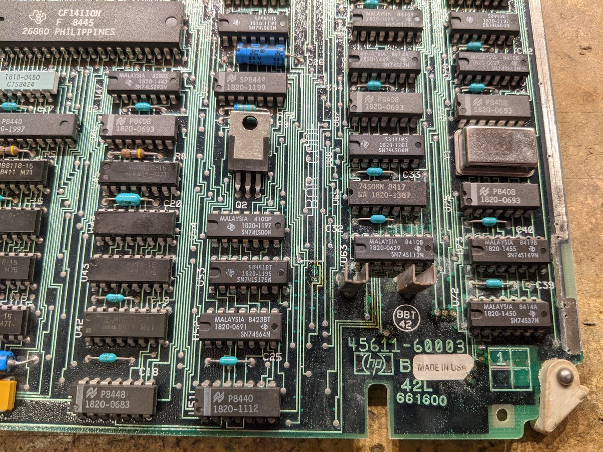
here's the RAM board.

turns out the data lines on the ROM chips also go to the RAM data outputs. a little continuity checking and I confirmed that RAM bit 0 is the bottom row of chips and bit 7 is the top row. based on the designators, I think bank 0 is on the far right.

the sockets are pretty sus

I swapped U42 and U43, and the memory errors went away!
now we get an error on the display.

weird, I hit enter and it seems ok. unlike the PC, with no boot device, it comes up as a terminal!

the display is very sharp, and the font is pretty high resolution.

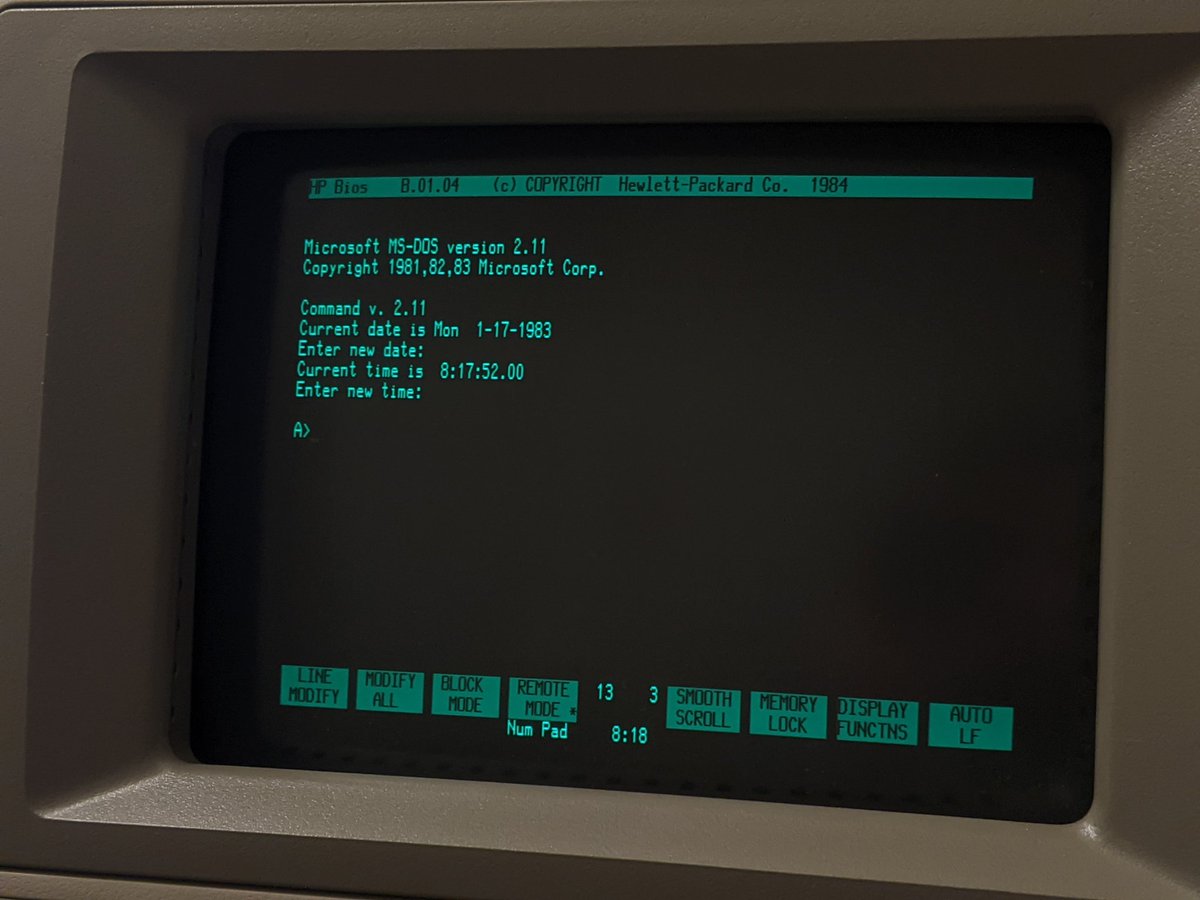
whoah it booted DOS!

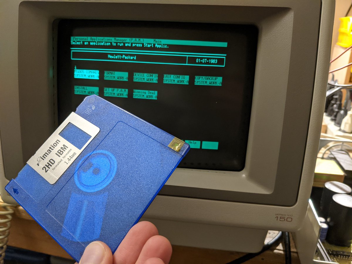
the interface isn't the regular command prompt. it is HP's P.A.M. which is their strange little "GUI"

looks like it is probably DOS 2.11.

the floppy drive doesn't seem to be working. i should dig around, i know i have a 9122 somewhere
hmm it seems it needs a 9121D, preferably. i might have one of those too. not sure if it works or not.
in the meantime, let's decode the 0200 error. sure enough: "interrupt controller problems"

hmm not really enough detail. i think the next step is to either find the ROM dumps or dump them myself, and figure out where this error code gets set. the code surrounding it should give me a clue.
hmm, i mean what is there to go wrong? maybe a stuck interrupt? but if that's the case, why would the computer work?

the red square puck makes an appearance

let's see what registers get written to

seems fairly innocuous. plays with the mask register a bit though after receiving some interrupts. maybe one of those is stuck? 0, 2, or 3? or perhaps my capture wasn't long enough and missed the error.

looks like the ROM enables a few interrupts in turn and tests to make sure they trigger. only int 4 does not. question is, what is int 4, and why doesn't it trigger?

the schematic calls it NSOCINT. it seems to be part of the thermal printer interface.

eventually it makes it out to the printer connector. looks like part of a bus interface.

maybe if I remove the printer it will work.

sure enough! so the printer is the problem.

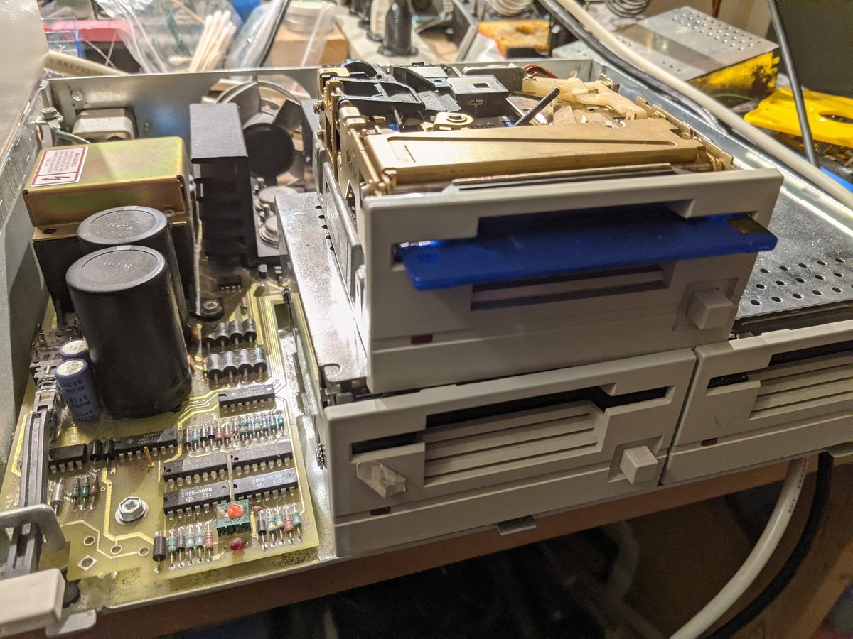
let's have a look at this printer.

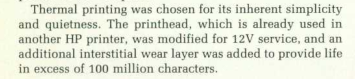
here's the circuit board. looks like it has a CPU on it. 1820-3211. it's an HP part number, and all of those are impossible to google because it's always reused by some crappy new product. 😛

no visible traces. the signals must all be in the inner layers, most likely to improve EMI.

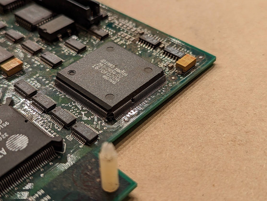
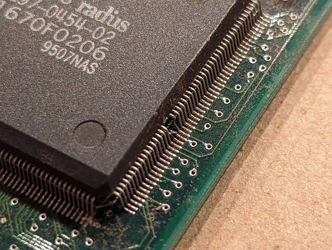
the CPU is odd, it's a Motorola part and almost looks like a mirror image of a 68hc05.

I could dump the ROM, and I'll probably do that at some point, but I want to see if I can fix it first.
noticed that the stepper motors are really stiff and hard to rotate, so I'm tearing it down to lubricate it and fix the belt tension

the spiky header thing on the right will be important later.
print head has a bit of corrosion. I hope it'll be ok.

the spiky header lets me tap into the data and control lines going to the printer.

huh, it appears to be sending the correct signal.

and now the display says "power on test failed 0004" which is a user RAM problem. also 3320 LED code is back, as well as a new one--5355 (CMOS checksum failure, but there's no battery, so that's expected)
couldn't clear the RAM error this time, even with chip swapping. maybe a bad trace or socket? I'll work on that later.
the printer works now. what did I do? well this test button may have been jammed down. that and the mechanism was frozen up a bit, preventing the head from reaching the other side and triggering an optical sensor. either could have frozen up the firmware.

oh yeah and i found paper for it! turns out the thermal paper from this old chart recorder fits perfectly. 🤗
https://twitter.com/TubeTimeUS/status/1273402380793425920
oh yeah and the 1820-3211 chip in the printer is a Motorola 68A01 CPU! the pinout even matches.

gonna attack the system RAM again. 3320 means bank 3, which I think is the far left column. 20 might mean bit 5.

my bank numbering was wrong, so I'm pulling memory chips to introduce individual errors on purpose. so far the bank ordering is... strange.

ok from left to right, it goes bank 1, 0, 2, 3. lol
U17. pin 10. it's address line A5, there's a bad connection between the chip and the socket.

ok it was actually a cold solder joint on that pin. the socket is ok.
zero errors! 🎉

now there's also an expansion RAM card that I have not tried yet

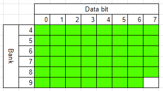
3F0A, 1408, 340A, 350A, 360A, 370A, 3902. lots of errors!
since these errors are *all* in the least 4 bits, I suspect that several RAM chips are misbehaving and writing to the data bus when they should not, stepping on adjacent banks. I removed all those chips and have been installing them bank by bank. bank 4 works ok now!

found 3 bad RAM chips. all the other banks seem ok now.

three replacements!

dangit there's one more bad chip. and those three were my last replacements lol

anyway here's what i did, in more detail. data bits 1 and 3 were bad in all the banks. i checked the buffer (74ls245) between the data bits and the expansion bus, and all of that was fine. no wires shorted, no wires open.

i had a hunch that there were 2 (or maybe more) chips that were corrupting data bits 1 and 3 for all banks, maybe by writing to the bus when they weren't supposed to. so i just removed all those chips except for the ones in bank 4.

suddenly bank 4 tested OK--the first error code i saw was for bank 5, because it was missing chips for bits 1 and 3.

i started filling it in more, and more banks started working.

then i ran into a bad chip. the errors started again at bank 4--but wait! i already know those chips are good, so it must be the one i JUST put in (bank 7, bit 3) that was causing a problem.

then it happened again. some of the chips were bad but did not screw up the entire bit line.
and now, after shuffling around chips and adding 3 replacements, i am here. missing one chip in bank 9 bit 7.
the chips are standard 4164 RAM chips, 150ns. i could probably borrow one from a RAM card in another computer, but i should just go buy some extras.
in the meantime, let's dump some ROM chips! this one is the character ROM on the video board. I'll install a socket for it just in case.

noticed some battery corrosion. I'll need to neutralize it with vinegar.

last RAM chip installed!

3810 and 3910 error. more bad RAM chips?
swapped THOSE chips out and now it boots with no errors!
and now I can install the CMOS battery. it's two N cells. very cute.

going to image the floppy disk. the PC board is a little custom version of the Greaseweazle that I built.

the disk is in good shape, so i got a clean read. the dark blue "pie slice" is wasted space, lol.

well, it has DOS-looking files on it. cool.

the disk isn't quite PC compatible though. it shows up as empty on a regular PC!

the boot sector is...a bit different.

best guess: the header record is technically correct, but it is missing the name of the filesystem type "FAT12".
all right, neither of these drives i have are compatible with the HP 150.

i need a 9121D, which *is* compatible. but wait! you say. they look identical!

but the 9122 drives use the CS/80 protocol, and the 9121 drives use the Amigo protocol. they are not compatible. and the 150 (the original, small version) only supports Amigo drives. 🙄

i guess i'll have to fix my 9133's floppy drive.
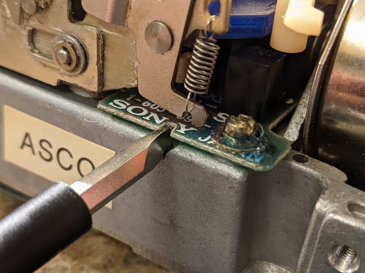
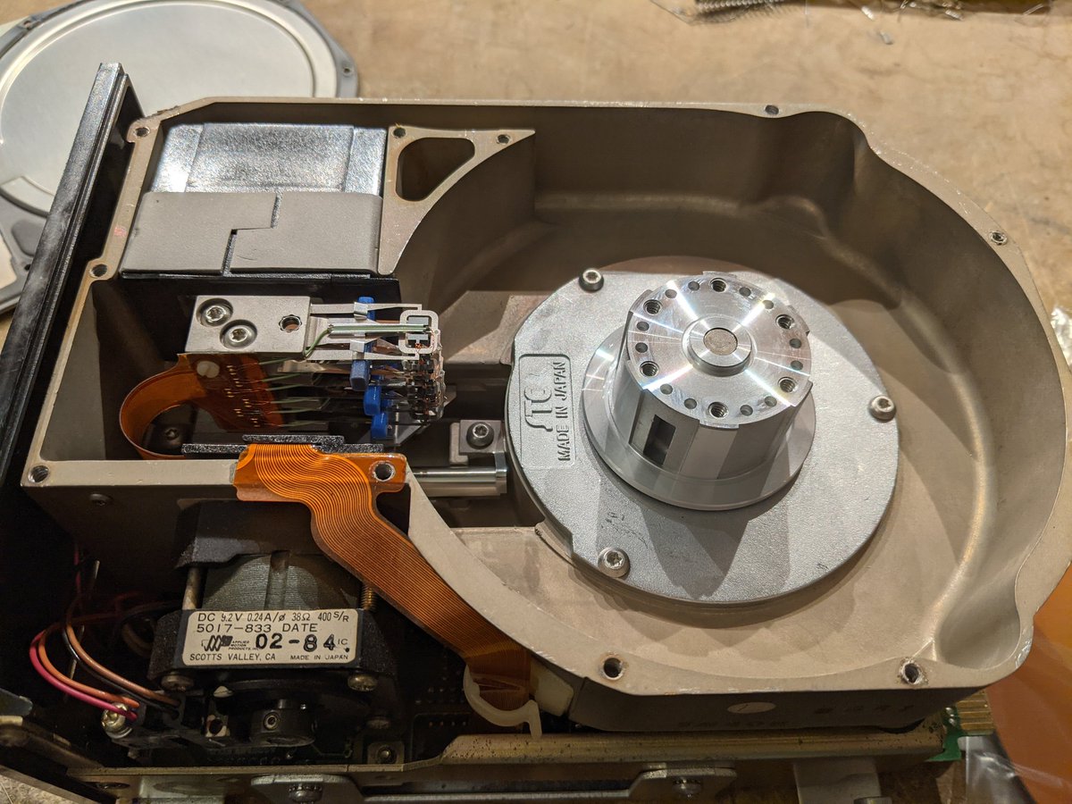
or swap in my spare Sony drive. check out that serial number! 100567.

uh oh, now the hard drive doesn't work, and i can't figure out how to get it to boot off the floppy.

also i misspoke earlier, the 9122 drives are ss/80, not cs/80 (a third protocol, smh)
oddly enough, the 9133D drive that i have supposedly uses SS/80, not Amigo. so how can that possibly work on the 150? it sort of implies that the 9122 should also work on the 150. 🤔
looks like my 150 has the 45611B model number, so it's a "150B" and *does* support SS/80.
this floppy problem is turning out to be harder than I thought

this Sony OA-D32W-11 mechanism is frozen solid because of the crusty old grease!

i have four of these drives:
2 in the 9122D: these appear to be working
1 in the 9133: the motor does not spin
1 spare: mechanically ok but no data seems to come out.
2 in the 9122D: these appear to be working
1 in the 9133: the motor does not spin
1 spare: mechanically ok but no data seems to come out.
i think the system disk isn't quite right. the 150 refuses to boot off of it.
ok so I took the disk image that I made using the Greaseweazle and... wrote it back out to a fresh disk, and now it works! this is with the 9122 drive.

smooth scrolling is weird.
I sorta want to try and implement it as a TSR for regular DOS, lol
it's got graphics! knowing HP, it's probably stored as HPGL

cards.

all games can be played entirely by touching the screen.

hmm look up and wow an hour has gone by

trying to fix the floppy drive. the motor gets stuck but if I spin it by hand, it starts turning.

good thing the service manual has a schematic

capacitors are fine. I think the motor driver chip has a bad phase. gonna do a little transplant surgery

surgery complete. let's see if it worked

no such luck. the motor spins but I think the alignment is off. that's a drawback of swapping stuff like this.
I love how the EPROM labels in this HP floppy drive have been created using a pen plotter (presumably another HP product)

since the motors don't seem to be mechanically interchangeable, I'm just gonna swap the driver chip.

well the chips are all fine. I swapped them all, and I swapped Q1. the shotgun approach isn't really working, lol

now for a more careful approach

it's this hall effect sensor! pretty sure anyway.

I was going to explain using this crappy diagram but I realized I ought to be putting this in my engineering notebook

the hall effect sensors are super old and don't have built in amplifiers. so this design just biases them in series. I compare the good motor to the bad, and the H2 sensor has a really big voltage drop across it!

motor coils

now it spins way too fast. and it's still getting stuck. wtf

the speed sensing coil wasn't soldered down properly. it runs at a reasonable speed now.

it's still a bit coggy. and the commutation is skipping some steps, but not as many as before. what if all the hall sensor chips have gone sketchy?
yeah I replaced hall sensor H3 and it works fine now. the index output also works now too!

the hall sensor replacements came from my spare drive.
the 9133 has a bunch of built in diagnostic tests. now it is running the format test.

so it passed the tests but failed to boot. strange.

looks like it can only read floppies that it has also written to. this is a clear sign of an alignment problem. so I'm not done but I've made good progress.
the service manual tells you how to align the drive. but i literally don't have any of the tools, except for the hex driver and the 4mm driver. what's a TOTSU screwdriver anyway?

well the SMC-70 is this glorious Japanese computer. it was apparently the first computer to use the 3 1/2" floppy drive. and apparently they made an add-on board which let you do the alignment without any separate pieces of test equipment.

this gets weirder and weirder
Nut Lock Paint 🔩
Alcohol 🍸
Sony Oil (??)
Sony Grease (???)
Nut Lock Paint 🔩
Alcohol 🍸
Sony Oil (??)
Sony Grease (???)

pretty sure this is the TOTSU screw. covered in Nut Lock Paint, natch.

the Geared Driver probably goes into the hole and moves the gear teeth on the stepper, and the Rotary Knob attaches to the shaft sticking out the back of the stepper.

may I present...Geared Driver and Rotary Knob!

alignment time!

the idea is to check and see how well centered the head is on the data track by looking at the analog amplitude of the signal from the heads. this signal is picked off CN107 pin 1, which is designed for this very purpose!
track 0 adjustment
ok it should be pretty well aligned. I use this little rig to manually step from track 0 to track 79 and back, ensuring that everything is aligned at both ends.

it passes the read CRC test!

it's still having trouble in the 9133, so let's try it in the 9122D. so far, it seeks, then reads a track, but it seems to hang. strange.

haha im dumb and tried to use a 1.44mb HD disk in a DD drive. it works now, at least in the 9122D.
the 9133 is still giving me grief but it is also behaving oddly. I think it's the way I'm trying to access the floppy disk as unit 0 instead of the hard drive.
let's try the 9122D and the 9133 at the same time! boot from 9122, try to access 9133.

gotta configure the drives first

no good. 🤔

maybe I need to look into these adjustments.

let's start with the PLL adjustment

oh yeah that's wrong. should be 500KHz +/- 1KHz.

better.

for the pulse width adjustments, i get utterly no signal at all! just flatline 0v. weird.

the docs are wrong, you have to move JMP0, not JMP1.
oh yeah I also need to find replacement standoffs for the HPIB connector. they're strange; they need a 6-32 thread to go into the connector and they need to be tapped for M3.5x0.6mm (yes, mixed metric and imperial!)

and I'm not done cleaning the corrosion on the video board. some of the traces and vias look suspicious
ugh, what a mess. glad I'm going in and fixing it.

yeah lots of corrosion hiding under the chips that needs to be cleaned up

clean! now I have to clean the chip leads and then solder them back down.

oh yeah that all worked out but I need to figure out how to solve the problems with the 9133 disk drive.

the official HP way to do this was to plug the drive into an HP-85 computer and run some special diagnostic software.
fortunately, I have an HP85. this neat machine is like a cross between a scientific calculator and a computer. it runs a fancy BASIC, and has a built in printer and tape drive.

the HP85 is also expandable. you could plug in this interface card and connect it to disk drives as well as GPIB test equipment. perfect for automating tests or measurements!

you could print out your test results with the thermal paper and tape them into your engineering notebook.

I would love to show you more of it, but it err stopped working just now. 😬

ok so here's where we're at: to finish the HP150 repair, I need to fix its 9133 disk drive. to do that I need to use my HP85. but that's broken so I have to fix that first.
I'll do that in a separate thread since Twitter doesn't have a good UI for yak-shaving.
got it working, and here's the thread!
https://twitter.com/TubeTimeUS/status/1490891179482750976
I've imaged the diagnostic software from hpmuseum.net. let's give it a try.

uh oh. 😬

so a bit of an admission: i already tried all this at @curious_marc's place this past weekend. and his copy (from the same source) has the same data error. it even happens with LIFUTILS under DOS.
here's the full link. it is a teledisk image of a floppy disk from someone who copied the contents of the original tape over to it. umm lots of opportunities for data corruption.
hpmuseum.net/display_item.p…
hpmuseum.net/display_item.p…
so let's look at the disk contents, shall we?
(i should also mentioned that i got a bunch of "CRC error in sector 17" errors in Teledisk when saving the image file to disk. there are like 2 of you who know exactly what this means)
so here is what the disk looks like. side 1 looks reasonable but what the heck is going on with side 0?

side 1 is full of formatted but blank sectors. 9 sectors total. this looks like a PC-formatted floppy disk.

side 0 has data. but what is the red sector? so there are 17 sectors total. 0-15 are 256 bytes, then it skips ahead to sector 17 which is only 128 bytes. ahh, i know what this is

this is some HP weirdness. instead of starting sector numbers at 1 like everyone else, they start at 0. they have 256 byte sectors for all but one sector, which is 128 bytes. this is a "media wear counter" sector.
the idea is to monitor how many times you access a track on the disk, and update the count. when you hit a limit, HP disk drives warn you and go read-only. you're supposed to make a copy of the disk.

the important part is that we can ignore these sectors.
anyway, when we get to track 70, the format goes back to the 9-sector PC format, so the HP drive only wrote to tracks 0-69. interesting.

according to hp9845.net/9845/projects/…, the 9121 format (single sided) is 70 cylinders, 1 head, and 16 sectors. at 256 bytes per sector this is 286,720 bytes, or 280KB.
but according to en.wikipedia.org/wiki/List_of_f…, the formatted capacity of a 3 1/2" HP disk is 270,336 bytes, or 264KB. which is it?
it is both! from the manual of the 9122, the drive reserves 4 tracks as spares for single-sided formats. 66*16*256 = 270,336 or 264KB.

i'm going to try to dump the teledisk file directly now.
first step is this old DOS program which unpacks the compressed Teledisk file.

then we run this converter program to generate an FDI file. but we're not done yet.

we run ANOTHER program to convert from the FDI file to an IMA file.

and then we switch from DOSBox back to regular Windows to run this program, which converts from IMA to HPI (which is supposedly just the flat binary of the disk)

hmm, the resulting file is 261,632 bytes long. that doesn't sound right
ok, let's try the linux lifutils to examine the image file. it definitely doesn't like something about it, but it finds the files in it OK.

hmm, sector 1022? that is 256*1022 = 261,632 which is the length of the file. a "regular" disk should be 1056 sectors long, so this image is indeed short by 34 sectors.

i think there are a few things going on here
1) the tape may have been corrupted
2) the disk it was copied to was corrupted to some degree
3) teledisk may have corrupted it on read
4) one or more of these utilities got lost in the weeds and copied in a PC or media wear sector
1) the tape may have been corrupted
2) the disk it was copied to was corrupted to some degree
3) teledisk may have corrupted it on read
4) one or more of these utilities got lost in the weeds and copied in a PC or media wear sector
maybe i could do some more work and figure out exactly what happened to this disk image, but i'd probably end up writing a bunch of disk utilities 😅
i think i'll just send an email to the hpmuseum folks instead.
@gts99503 noticed that some tracks have mislabeled/missing sectors.

tbh i have no idea how this could have happened. there cannot be a sector 116. the CRC is correct, though.
anyway, one of the programs loads fine, so I'll use it.

it can see the drive!

btw this drive is still making sad noises on power up. you can hear it seeking all over the place.
bad boot sector.

sure enough, this disk image is damaged in exactly the ways we found but the program can repair it!

nice.

here we are again.

the alignment looks good. track 0 seems ok. maybe I just need to reformat it.

before i start digging into that, i'd like to check the disk image that i made earlier, just in case there's any interesting old software here.
so this doesn't look like a boot sector.

but this does. hmm, what are the first C000 bytes on the disk?

maybe the spare sector table? there appear to be 6 copies with identical data, just in case one of the first few tracks is bad, i guess.

doing a little math. C000=49152. divide by 256 bytes per sector, divide again by 32 sectors per track, and we get 6 tracks. there are three platters in this drive (with 6 sides). this is the first cylinder on the drive!
somewhere they have a place to store the spare sectors along with a mapping table. maybe this is it.
anyway let's go to the interesting part: the partition table.

EB 1C 90 is similar to a traditional DOS boot sector. it is code: JMP 0x1C (relative) followed by a NOP. then there is the volume label, 8 bytes which are "HP150 "

the relative jump goes to this code: 90 F4 EB FD which is NOP, HLT, JMP 0x1. meaning the HP 150 does not boot like a regular DOS PC, and this is just a stub of code that halts any CPU trying to execute it.

the data in between is the bios parameter table. it's mostly correct. but the media descriptor lies and says this is a floppy disk.

looks like there's no traditional partition table. hmm.

i don't know what the data in the middle is. i don't think DOS 2.11 did partitions.
moving on, it looks like we have a file allocation table in the very next sector!

decoded it a little bit just for fun.

and here is the directory table! finally some recognizable text.

the only interesting thing on this hard drive appears to be this incredibly old version of WRQ's Reflection. i see zero info about it so i think it is unpreserved.

fatcat hates this disk image so i may need to 1) trim off the first track and 2) make the partition table more agreeable to it. github.com/Gregwar/fatcat
umm i ended up writing ~100 lines of crappy python that does this. not much more work to create the file structure and extract all the data, lol.

instead of messing directly with my computer's filesystem, i just used Python's zipfile library to stuff it all in a ZIP archive.

wow, that was rather surprisingly easy. the FAT filesystem is not as complex as i thought (at least, FAT12 is not)
wanna see my horrible code? github.com/schlae/defat12…
meanwhile I've been running the drive upside-down for a few hours to let the lubricant drain back into the bearings. the drive is a lot quieter now.

time to reformat! hopefully the drive will be reliable after this.

the design notes for the 9133 indicate an interleave of 10 for use with the HP150.

uh oh

error AB is "more than 6 bad sectors on one track"
another dead end? i have a few more things i could try:
1) try a low-level format in a PC
2) adjust the track 0 sensor to shift the entire set of tracks by 1/2 track, write new data in between the old tracks
3) take apart the sealed drive and do a platter swap with another drive.
1) try a low-level format in a PC
2) adjust the track 0 sensor to shift the entire set of tracks by 1/2 track, write new data in between the old tracks
3) take apart the sealed drive and do a platter swap with another drive.
if i do #3 then i could also attempt a bearing swap, since they started to make noise again after running right-side up.
i mean other folks have tried crazy stuff like this.
https://twitter.com/wrljet/status/1476311304013066240
👀

I took the lid...
🙌
...off
🙌
...off

looks like some very fine scratches. this probably explains all the bad sectors.


if i want to swap platters, i need a way to spread apart the spring suspension of the read/write heads. there must have been a tool used during the manufacturing process. 🤔

doing a little patent research. i didn't realize that "winchester" implies that the disk is lubricated.

apparently lubricated with a fluorocarbon film. interesting.
anyway, what i need is a "hard disk head comb" and the ones i can find are all made for more modern drives. guess i'll have to design my own.
perfect! I just slide in this little 3D printed block, rotate it 90 degrees, and the heads pull back from the platter.

first platter removed. the hole in the side of the spacer on the spindle is for airflow.

platters are all gone!
each hard disk platter has a hand-written serial number. this one is 73423-57. not sure what the +1 is. maybe an inspection mark?

sadly the hub is pressed onto the motor shaft. the bearings will be in the middle part that I can't access. I could certainly remove it, but the distance between the base and the outer case is a critical dimension

so tbh i'm not really sure where to go from here. i could track down some other dead Seagate drives for a platter swap. but then i'd be starting up a Seagate drive repair shop at that point, lol. i could also remove the scratched platter and turn the drive into an ST-412.
the 9133 can also host ST-225 drives which store 20MB. and i have one of those that i'm not really using, so maybe that's a better approach.
same energy


(image credit for the false front building: commons.wikimedia.org/wiki/File:Side…)
hmm, if Weird Stuff Warehouse was still around (RIP), i'd just go over to this section of the store and dig up old Seagate drives. i miss that place.

all right, I decided to swap in my ST-225. it is doing the low level format right now. I had to change some jumpers that turn this drive from a 9133D into a 9133H.


low level format and verify succeeded! now time for the HP150...

one of the stranger ways I've formatted a hard drive. yeah, using a touchscreen.


come to think of it, it's really strange having to low-level format the hard drive FIRST using a totally different computer that doesn't even use the same CPU architecture.
and it's DOS 2.11 booting from the hard drive, which (naturally) gets the drive letter A.
weird issue: configured as a 9133H, I cannot access the floppy drive at all, even though passes all the internal diagnostic tests. I think the 9133 firmware may have a bug. 09133-89103 and 09133-89203.


I'll fix the floppy issue later. but look! I have DOS 3.2 installed now. drive A is the hard drive, as it should be 😅

I found a problem with the print head for the thermal printer built into the top of the computer. take a wild guess what it is 🙁


i'm a little worried that one of the driver outputs got stuck and overheated the head.
wow, the flex cable is connected to the print head using wire bonds, like a chip

giving up on the printer for now. i "just" need to find a new print head. or a new printer
instead, it's time to get this modem going!

but first i will dump the firmware just in case.

a good read! i looked up the author of the firmware and he has a LinkedIn account. seems he was very busy after writing modem firmware!

the modem does not use the expansion bus signals except for power. the serial connection uses this weird little loopback cable.

all right, time to call another modem! maybe i'll call bbs.retrobattlestations.com
weird, it doesn't work. so is it a problem with my ATA, my VOIP provider, this modem, or the BBS itself?

my ATA is the Grandstream HT802. i have turned off echo cancellation. apparently this is important to avoid confusing the modems.

PCMU is the preferred codec, aka G711u. again needed to avoid confusing modems.

no Voice Activity Detection. gotta keep them modems happy.

i'm going to try bumping up the TX and RX gains.

boom! it connected. too bad about all the data corruption lol

anyway, giving up on that for now. back to the printer. the print head seems to be the same (or similar) to that used in the 2671A. and here is one on everyone's least favorite auction site!

oh. 😐

no matter, they probably aren't compatible--they had to modify the print head to work at 12V.
well that was hard. i modified the flex and shifted it over 3 spots. the print head has 15 elements but the printer only supports 12. maybe the elements in parallel will improve the common connection...

after cleaning up the huge mess of flux it looks a lot better. it was hard because the ceramic circuit uses aluminum conductors. i wonder if it'll work?

welp, all i get are some faint marks, so i guess the resistance is still too high. 🙁

• • •
Missing some Tweet in this thread? You can try to
force a refresh


