Ever wanted to debug your microcontroller over USB-C?
(I'm talking JTAG/SWD, not just USB!) If you already have a USB-C connector, there's no need to have an additional connector to program (or tag-connect pads, which are super nice)
Here's one way to do it: 🧵
(I'm talking JTAG/SWD, not just USB!) If you already have a USB-C connector, there's no need to have an additional connector to program (or tag-connect pads, which are super nice)
Here's one way to do it: 🧵

The USB-C specification(usb.org/sites/default/…) has a section B - Debug Accessory Mode. It explains how to "support" DAM. In short, if both CC1 and CC2 are pulled up (usually, only a single one is) a device can enter DAM. While in DAM, the following signals can be repurposed:

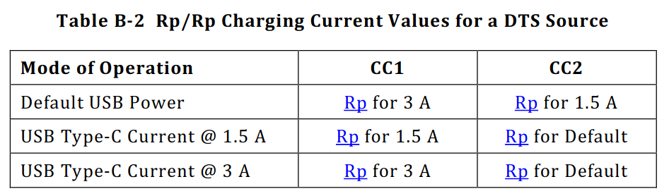
Normally, CC1/CC2 are used to determine orientation as well as power delivery information. For this thread, I'll just focus on "dumb" PD with termination resistors. Depending on the source's pull up resistor (Rp) value, the source can advertise various charge currents.

USB-C cables only pass through CC1. In order to use DAM, we need to have a USB-C plug (or custom cable) to connect both CC1 and CC2. If the device is in DAM, how do you know the charge current? There's another table for that :D
DAM doesn't specify any standard pinout. It's up to the designer to figure that out. Here's what I came up with:
RX1- - SWDCLK
RX1+ - SWDIO
RX2- - SWO
RX2+ - NRST
SBU1 - VCC(target)
SBU2 - GND
USB D+/D- stay connected the usual way.
RX1- - SWDCLK
RX1+ - SWDIO
RX2- - SWO
RX2+ - NRST
SBU1 - VCC(target)
SBU2 - GND
USB D+/D- stay connected the usual way.
This pinout means that the connector is not reversible. Using the TX and RX lines in a particular way would allow for that, but I chose not to do that (I'll explain why later.)
Technically speaking, a device should not enter DAM unless CC1/CC2 are both pulled up.
Technically speaking, a device should not enter DAM unless CC1/CC2 are both pulled up.
In order to do this "properly", we can use a two comparators(op-amps in my case), an AND gate, and a switch (TMUX1511, in this case). The comparators detect when both CC1/CC2 are pulled up. If both are, the AND gate enables the switches to connect all the signals.

The comparators are needed because the CCx pull-up might be as high as 56kOhms, which results in a CC voltage of ~0.4V, which is likely below the AND gate's threshold. A simple resistor divider is used to set the comparator threshold level (I set it ~0.2V)
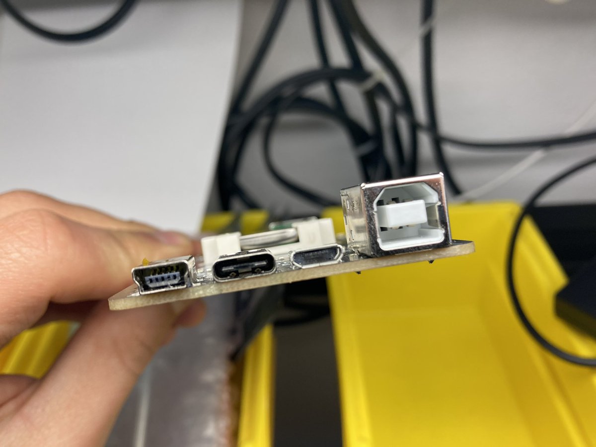
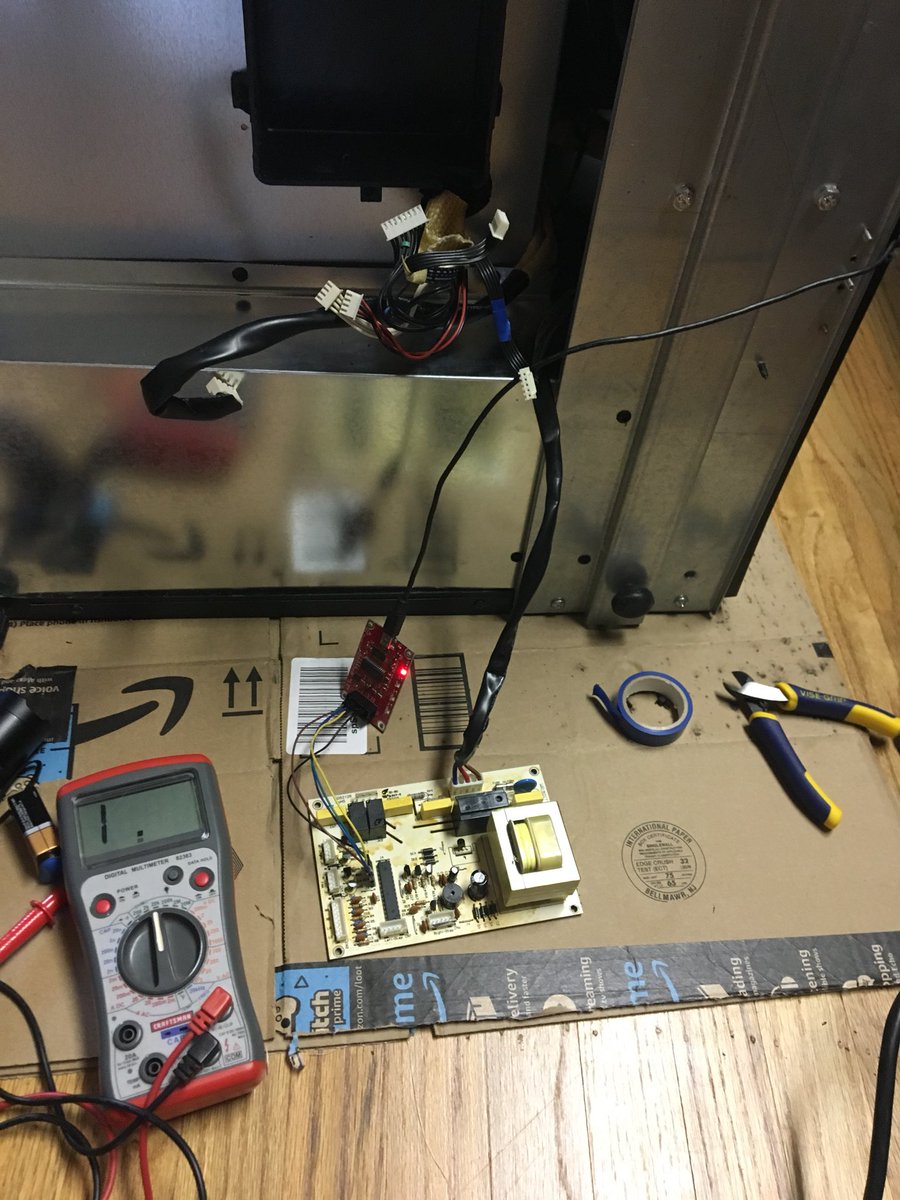
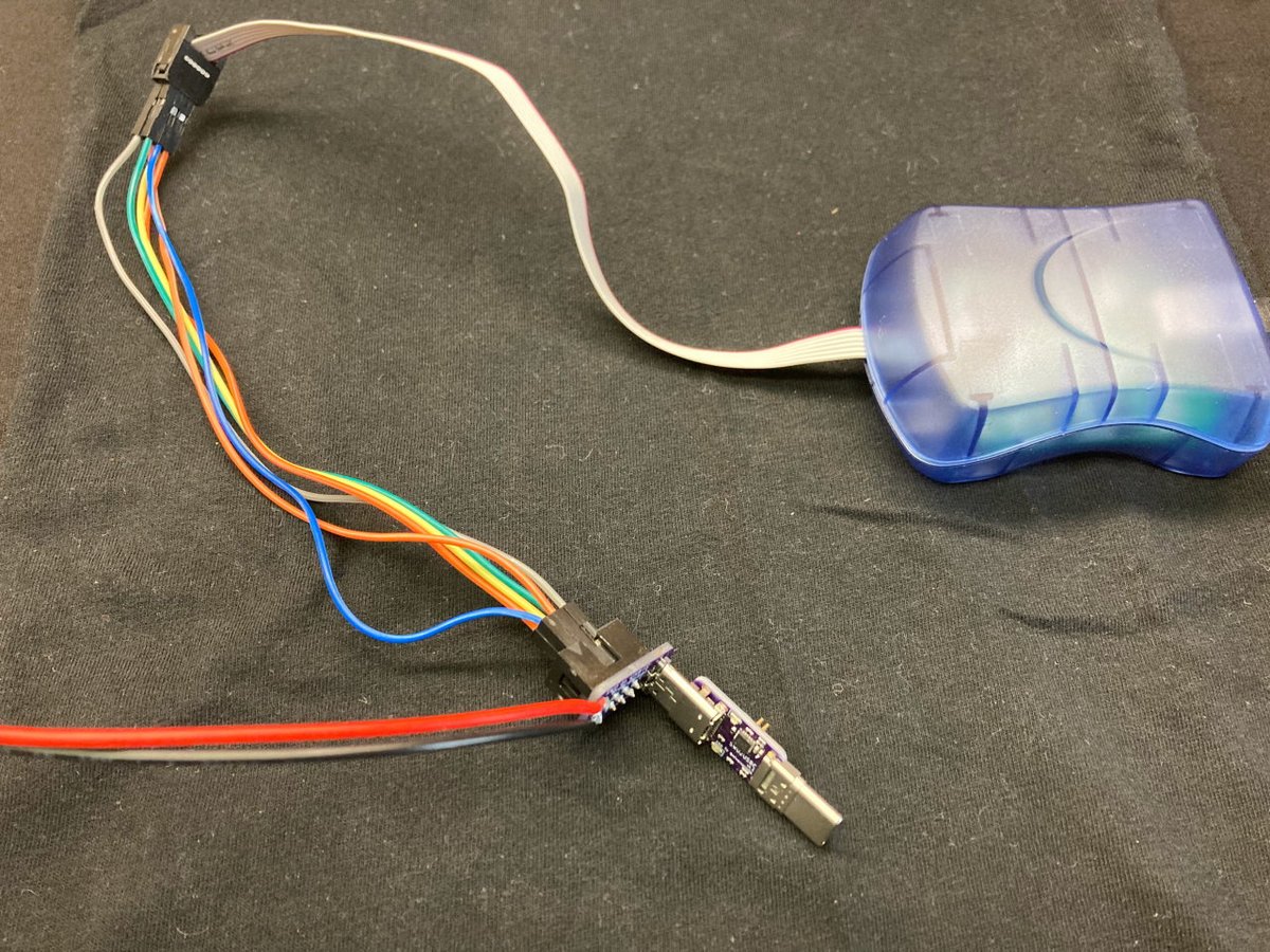
In order to test all this, I first used a USB-C plug breakout board with a few wires 😬
On the other side, I hooked up the circuit mentioned above. (I can't show the main circuit, unfortunately).
The setup worked though! Time to make some custom boards :D
On the other side, I hooked up the circuit mentioned above. (I can't show the main circuit, unfortunately).
The setup worked though! Time to make some custom boards :D

I decided to make a board that passes through power and USB, but hijacks the CC1/CC2 lines to enable DAM. I used an attiny24a(in stock!) to read in the input CCx lines to determine the input charge currents and set the appropriate downstream CC1/CC2. I used the wrong footprint 🤦♂️


I hard-wired the CC resistors and it worked :D
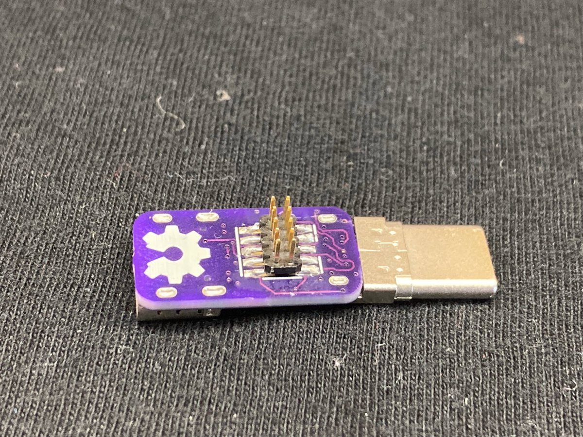
Here's the fixed version. It uses the SBU1/SBU2 signals (VCC/GND) to light up a green or red LED to let you know if it's plugged in wrong. It has standard SWD pins for debugger. The only problem is... I have to program the attiny24!
Here's the fixed version. It uses the SBU1/SBU2 signals (VCC/GND) to light up a green or red LED to let you know if it's plugged in wrong. It has standard SWD pins for debugger. The only problem is... I have to program the attiny24!

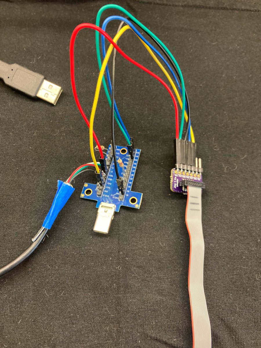
So I made another programmer over USB-C 😂
This one uses SPI instead of SWD. I also got the MISO/MOSI lines flipped, so had to use some jumper wires to program.
This one uses SPI instead of SWD. I also got the MISO/MOSI lines flipped, so had to use some jumper wires to program.

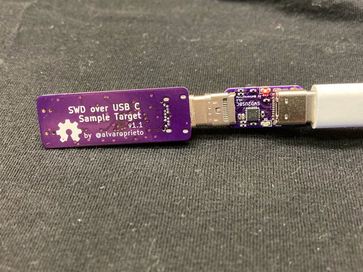
I decided to make a test target with all these features. It's just an STM32L4 😎 with USB and a couple of LEDS (along with all the CCx detection fun). You can see how the LED is red when it's plugged in backwards.
After much pain soldering on those USB-C connectors, it all works!
After much pain soldering on those USB-C connectors, it all works!


Ok, so back to why I didn't want to make the pinout reversible. Following the USB spec is nice and all, but for hobby projects... 🤷
What if we ignore all of the CCx detection stuff and just permanently wire the SWD lines to the USB port? Saves us several components and space!
What if we ignore all of the CCx detection stuff and just permanently wire the SWD lines to the USB port? Saves us several components and space!
If we'd used the TX1/2 lines of the USB-C port, the host would send some test pulses on connection to try and negotiate USB3 (or something else). Since we only use the RX lines, there's a low chance of the host signals causing unintentional trouble over SWD!
If we chose to go this direction, the footprint/component requirements to do this are zero! You'll still need an adapter board to connect your debugger, but that's it! (Maaaaybe I'll start selling these soon if there's any interest)
Hope this was useful! :D
Hope this was useful! :D
• • •
Missing some Tweet in this thread? You can try to
force a refresh