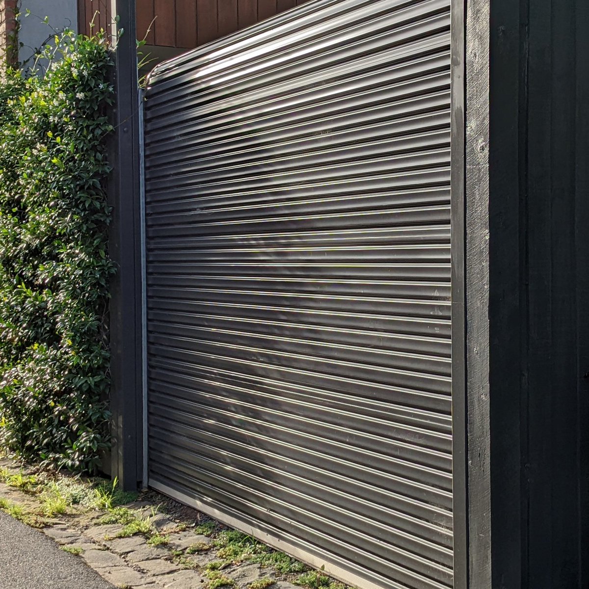
It's an external one on to a side lane, so the actual motor is very self contained and weather proof. There are no extra control wires or anything available. It does have a remote though. 

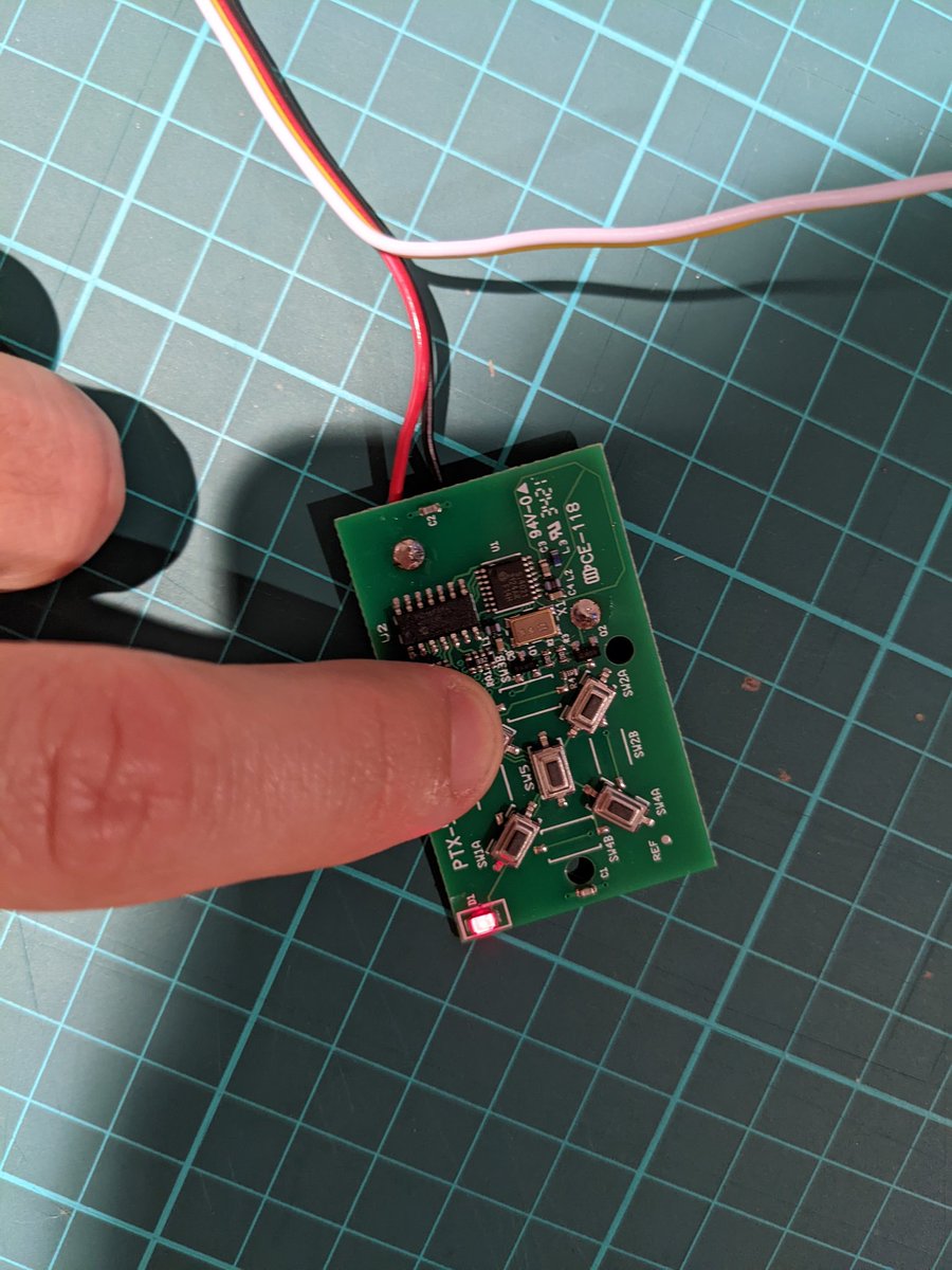
The back of the remote says it's an ATA PTX 5v2. Quick Googling says it's actually quite secure. Each remote has a unique 128-bit keyed rolling code.
garagedooropenerremotes.com.au/wp-content/upl…
garagedooropenerremotes.com.au/wp-content/upl…
The shared key encryption would be very annoying to replicate from scratch. Sooo, I just bought a second one, paired it, and am now pulling it apart.

My goal is to just wire up an external control to the existing button, and give it a fixed power source (instead of battery). The existing remote can provide the rest of the smarts for me.
Step 1 is to trace some of the wiring. Do the switches go to common ground, high, or something else? Where are easy places for me to solder extra wires on to?

I'm just using my trusty multimeter on "connectivity" mode. Touch the two probes to somewhere where there's no resistance and it beeps.

There are four buttons on the remote. First up, I want to work out which side of the switches are common vs. unique. Turns out all of the inner terminals are common, so it's the outer sides of the switches which are the signal side.

Where does the signal line go for the switch I want? Hold one probe to the known point, and just run the other probe around. It runs to here:

It's a bit hard to get a photo of that chip, but with much manipulation, here's a kinda-readable model number: PIC16F684.

Thank you Google. Here's the data sheet for it: pdf1.alldatasheet.com/datasheet-pdf/…
I don't strictly need it, but it'll be interesting to know the behaviour of that pin.
I don't strictly need it, but it'll be interesting to know the behaviour of that pin.
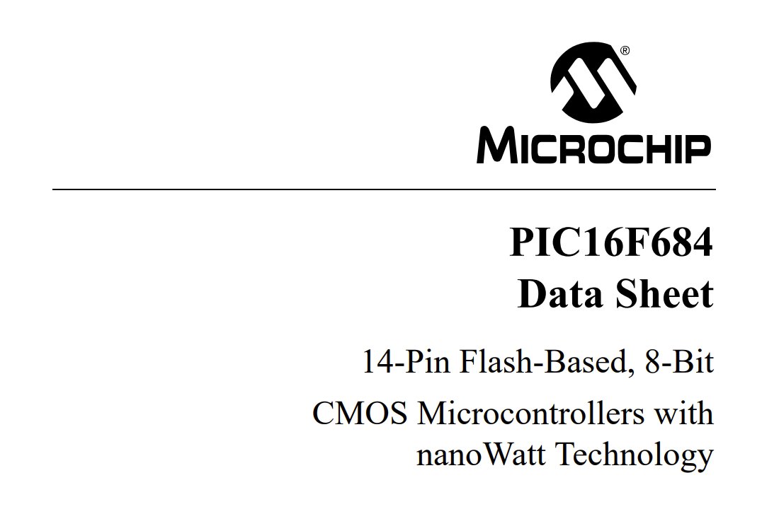
The signal side of the button I care about goes to pin 12, which has a stack of different capabilities. These look like very cool little low-power microcontrollers.

I suspect it is being used as "I/O w/programmable pull-up and interrupt-on-change". It's interesting to note that the pin has a built-in pull-up.

Getting away from that for a sec ... Let's trace power. VDD of the microcontroller is _not_ connected directly to the 3v net, so there's some other power control going on here. If I hold a button down, the chip gets its power.

Ok, I know enough to solder on some extra power wires at least. But it's surface-mount-sized soldering and my hands shake like crazy, so first ... Scotch.

Goodbye watch battery holder.

No more batteries required after this. Multimeter says connections are good. Now for the signal input...


Curve-ball: it's not just two mounting points for the positive side of the battery mount; it actually relies on them both being connected as a common rail. I can't just solder a wire into one of them, I have to add a jumper.

Second attempt on power, now with extra jumper cable:


Add 3v of external power, press a button, and a light goes on! So that's progress...
That's enough for tonight. Signal inputs tomorrow…
Back at it… I know that 'signal' side of the switch goes direct to an IO pin on the microcontroller, but I need to work out where the 'common' side of the switches all go. Do I just pull the IO pin high? Low?
Using the multimeter, I can't find any obvious link from the 'common' side of the switches to either Vdd (positive) or Vss (negative), even allowing for a pull-up/down resistor in line.

It's too hard to visually trace on this board, so I'm reliant on just probing around with the multi-meter to see what pops up where. The common side of the switches all connect to this pin:

Google suggests that it's a PNP transistor, and that pin is the emitter. Makes sense for a three-pin package; they're either transistors or voltage regulators usually. Somehow, this will be driving the low-power wakeup.
alltransistors.com/transistor.php…
alltransistors.com/transistor.php…
One other quick test… is the switch just a SPST, or is there some kind of DPST thing going on?
littelfuse.com/technical-reso…
littelfuse.com/technical-reso…
Easy way to test is just jam a small jumper across the visible pads and see if it creates the same behaviour. It does, so that's just SPST.
(Does that SPST/DPST make sense for a push button? 🤷♂️ Best terms I have.)
(Does that SPST/DPST make sense for a push button? 🤷♂️ Best terms I have.)
De-soldering those switches will be hard at the best of times, and it's not yet Scotch-appropriate-o'clock, so I'm just going to try soldering extra wires either side of the switch. A quick test on a second switch seems to work fine:

All done. My secondary garage remote now has external power and signal inputs exposed via a nice ribbon cable with a Grove connector.

What does a Grove connector plug straight into? My favourite little microcontroller/dev-kit, the @M5Stack Atom Lite. 🤘 tatham.blog/2020/08/22/mak…

Except I need 3V not 5V of supply, and will need a transistor or something between the white and yellow, sooo … not such a useful connector to have attached in the end. 🤦♂️
A quick jig on the breadboard has it working. I can draw 3V off the M5, but just not from the Grove connector. Touching the jumper on the breadboard makes the remote trigger.

I found a bag of BC547 transistors in a box, so I'm going to use one of them to act like the original switch.
components101.com/transistors/bc…
components101.com/transistors/bc…

Added the transistor to the circuit on the breadboard. The existing switch is in parallel - across the collector and emitter. When I touch +3v to the base, the remote activates.
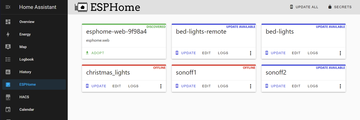
Now to make some firmware and drive it from the @M5Stack via Wi-Fi. I'm going to use @esphome_, per tatham.blog/2020/08/30/esp…
@M5Stack @esphome_ @esphome_ is *way* easier these days, vs. when I recorded that video. web.esphome.io makes it an absolute breeze. Web Serial lets me bootstrap the firmware right from Edge.

It has been bootstrapped with enough firmware that I can now disconnect the @M5Stack from my laptop again and do everything else from here via over-the-air @esphome_ updates.
@M5Stack @esphome_ Hello, Wi-Fi addressable roller door. (With 100% local control, no rando clouds/apps, and known protocol/security/firmware.)

Click the button in @home_assistant, and the remote triggers. 🤘
I've added a pull down resistor (the transistor base was floating otherwise), and moved it to a smaller breadboard. This can just run like this for a day or two until I've proven it out, then I'll move it to a proper little box.

For now, that's an entirely working solution. 🤘
All local control. No external wiring. Still secure - same rolling code for the door, and known local firmware/network.
All local control. No external wiring. Still secure - same rolling code for the door, and known local firmware/network.
• • •
Missing some Tweet in this thread? You can try to
force a refresh