The HIMARS mobile rocket launcher has been in the news as a powerful new weapon in Ukraine. I thought a teardown of its internal electronics would be interesting. (Nobody would give me a HIMARS so this is a "virtual" teardown.) Laser gyros and other technology ahead... 1/57 


The HIMARS vehicle holds 6 rockets in a launch pod, which it quickly swivels left and right, up and down to aim at the target. Nicknamed the "70km sniper", HIMARS rapidly fires highly-accurate rockets over long distances and drives away before the enemy can respond. 2/57


HIMARS (High-Mobility Artillery Rocket System) is designed for speed and logistics. Its integrated boom and hoist quickly load the 2-ton launch pods, swapping 6-rocket pods in a few minutes. The boom forms the distinctive "handle" at the front of a HIMARS launcher. 3/57


HIMARS can be delivered to almost any location. It is designed to fit inside a small C-130 cargo plane, which can land on roads, dirt, or snow. The fit is so tight, you have to fold in the HIMARS' side mirrors and let air out of the tires. 4/57
Now the electronics.
Now the electronics.


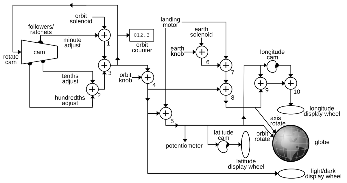
HIMARS is controlled by the Universal Fire Control System, composed of multiple boxes of electronics networked together. Most of these are mounted in "sponsons", compartments on the sides of the launcher. I'll discuss these components. 5/57

The "HIMARS Universal Launch Interface Unit" (HULIU) is the hub of the fire control system, managing internal and external communication. It controls and monitors system power, hydraulic fluid level, temperature, and pressure. It contains a general-purpose networked computer.

Rockets are fired through the Universal Gunners Display Unit, a screen and keyboard that have gone through various revisions. Most operations are controlled by programmable function keys surrounding the screen. Red-covered switches are Power, Arm, and Fire. 7/57


The UWIU (Universal Weapons Interface Unit) provides control signals to the rocket pod, directing and launching the rocket. It contains the ballistics targeting algorithms, aiming the rockets. It also downloads GPS info and software updates to the rockets before launch. 8/57

When a pod of rockets is installed, two cables from the UWIU are connected to the lower rear of the pod. One cable provides "discretes", signals for getting status, igniting a rocket, etc. The second provides GPS information, programs the warhead, and provides power. 9/57


The HIMARS has four pod connectors, even though the rocket pod only uses two. Larger ATACMS missiles use two more cables for more power, high-speed Ethernet and data. 10/57

The rockets spray hot, corrosive exhaust over the HIMARS when launched. The crew is protected by louvers over the windows and a chemical air filtration unit (CAFU). The corrosive residue must be cleaned off the HIMARS, especially the cable connectors. 11/57


When installing a rocket pod, a soldier uses the UWIU to check for shorts or stray voltage in the cables before attaching them to the rockets. This "Short/No Voltage Test" (SNVT) ensures that rockets aren't accidentally triggered by stray voltage in the cables. 12/57


The SNVT test may seem overly cautious, but stray voltage fired a Zuni rocket on the aircraft carrier USS Forrestal (1967) triggering a fire and explosions that killed 134 sailors and injured 161 including John McCain. 13/57

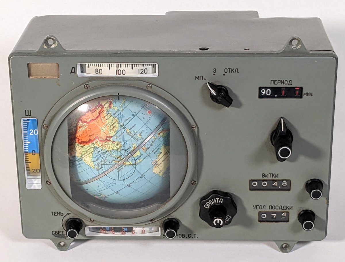
Next: the Universal Positioning Navigation Unit provides navigation for the HIMARS: GPS, inertial navigation, and odometer. It uses RL-34 ring laser gyros and accelerometers (bad photo). 14/57


In 2011, HIMARS upgraded to GE's PowerXtreme PPC7EP single board computer. It used a 1-GHz Motorola MPC7448 PowerPC processor. This high-performance processor was built using 90nm silicon-on-insulator technology. Each HIMARS uses three of these boards and a PMCGA4C graphics card.


Software is loaded into the HIMARS from the Ruggedized Memory Unit. This is just a 1 GB USB flash drive in a patented militarized package. The round military connector has two pins cut short because USB must connect ground before data. 16/57


HIMARS uses three main communication systems: a VHF/FM radio, a high-frequency (HF) radio for longer range, and a digital situational awareness system. (These are the American systems; Ukrainian forces use different radios.) 17/57
The first radio system is two VHF/FM SINCGARS radios (one for data, one for voice). These radios are advanced, crammed full of boards with FPGAs, DSPs, etc to provide cryptography and other features. 18/57

The second radio is the HF radio, mounted in a vehicle adapter. It has encryption, digital voice, tactical internet, software-defined radio. Many HIMARS have a big loop on top of the cab: a Harris RF-3134 high-frequency loop antenna for long-distance voice and data links. 19/57


The third communication system is Joint Battle Command Platform (JBC-P), a digital networked situational awareness system. Sort of like "Find My Friends", it shows military units on a map, along with tactical chat. This evolved from Blue Force Tracker, FBCB2, and other systems.


JBC-P runs on a variety of hardware platforms: Mounted Family of Computer Systems (MFoCS), Joint Version-5, Military Rugged Tablet Plus. The Army's next generation will be Mounted Mission Command, based on Android. 21/57


The digital system uses L-band satellite links as well as digital radio. The photos show two different satellite transceivers. Digital security is provided by the KGV-72, a programmable in-line encryption device that costs $2,565.58. 22/57


HIMARS is a descendant of the older MLRS (1980), still in use. MLRS is a double-wide launcher on tracks that holds two pods. MLRS was heavily used in the Gulf War (1991), firing thousands of cluster-bomb rockets. 23/57

The electronic systems in the original MLRS launcher used 3 Z8001 processors (6 MHz) and a Z80 processor (2 Mhz). This block diagram shows how the electronics units were connected to the Missile Launch Pod Assembly (M/LPA). 24/57

The MLRS was upgraded to the Improved Fire Control System (1992) with object-oriented software in the Ada language. It used 8 Intel 486DX processors at 32 MHz, but Intel stopped supporting this processor, requiring a hasty switch to the Motorola PowerPC processor in 1997. 25/57


Now MLRS and HIMARS are being upgraded to the Common Fire Control System. The first MLRS M270A2 with new software, an improved armored cab, new engine, transmission, and launcher was delivered to the US Army just a few days ago. 26/57

Next, the rockets. HIMARS supports a family of rockets but the important one is GMLRS, a GPS-guided rocket with 84 km range and a 200 lb explosive warhead. It is guided by an inertial measurement unit and GPS. Accuracy is secret but very good; an early test reported 2.1 meters.

The GMLRS rocket is guided by a compact guidance set that uses GPS and inertial measurements. The grapefruit-sized HG1700 system combines a NavStrike™ GPS receiver, a Honeywell Inertial Measurement Unit, a CPU board, and a power board. It weighs 4 kg and uses <25 watts of power.

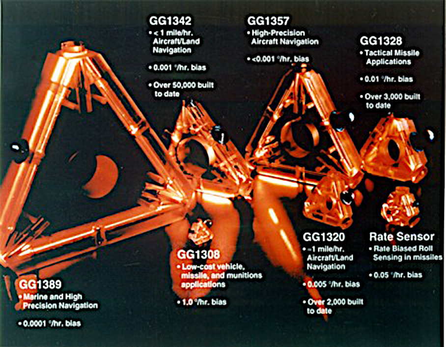
Inertial measurement tracks the position by keeping track of rotations and accelerations internally, so it can't be jammed. Three ring laser gyros measure rotations around three axes, while three orthogonal accelerometers measure acceleration. 29/57
A ring laser gyro (RLG) shoots laser beams in opposite directions around the triangular cavity, producing interference fringes. If the gyro rotates, the lasers shift and the fringe pattern changes. GMLRS uses Honeywell GG1308 ring laser gyros, very small, just 0.8" on a side.
The CPU in GMLRS was a Motorola MPC8260 microprocessor with PowerPC 603e at 200 MHz along with 16 MB of flash and 32 MB of RAM. (Apple, Motorola, and IBM created the RISC PowerPC in 1991.) Over a dozen serial controllers communicate with the rocket, and Ethernet to the launcher.
The problem with an IMU is that small errors accumulate. If your starting angle is off by 3 milliradians, the error is 3 meters per km. So a 49 km flight means you miss by 147 meters. GPS provides a huge accuracy boost. 32/57
The NavStrike GPS receiver in the missile is much more advanced than consumer GPS. It acquires position very quickly, handles high velocity, and has military encryption and jam resistance. It originally used a large tamper-resistant multi-chip module with GPS and security chips.


GMLRS guidance (and the HIMARS launcher) are being upgraded to support GPS M-codes, which are more resistant to jamming and spoofing. This is implemented through the NavStrike-M board, a replacement for the old NavStrike board. 34/57


The compact Inertial Measurement Unit is 3.7" diameter and 1.9 pounds. Three boards: sensor card, digital card, and microcontroller card. The accelerometer/gyro unit contains 3 orthogonal accelerometers and laser ring gyros, and high-voltage laser power supply. 35/57

The accelerometers are Honeywell RBA-500 Vibrating Beam Force Transducer Accelerometers. Each uses a pair of vibrating quartz beams where the difference in oscillation frequencies depends on the applied force. 36/57

The guidance system uses a Kalman filter to combine IMU and GPS data. This clever algorithm from the 1960s combines multiple measurements while accounting for inaccuracy. Even your phone uses a Kalman filter to determine location. 37/57

The guidance system ensures that the missile knows where it is at all times. 38/57
The guidance system is powered by a lithium thermal battery. The electrolyte is solid so the battery won't deteriorate in storage. Just before launch, pyrotechnics inside the battery melt the electrolyte. The battery then provides electricity like a normal (but hot) battery.

I think that GPS guidance made HIMARS possible. The tracked, heavy MLRS system can rapidly fire unguided rockets. But the truck-based HIMARS rocks severely when launching, so unguided rockets would go way off course. 40/57
The Electronic Safe and Arm Device ensures that the warhead detonates at the target, but not before. One FPGA circuit verifies arming commands from the guidance system. An independent FPGA checks an accelerometer so even faulty guidance signals can't detonate the warhead. 41/57


The ESAD uses a Motorola MMA1201P Analog Accelerometer, measuring up to 40G of acceleration. It ensures that the missile accelerates for at least 5.7 seconds after the umbilical disconnects. Thus, the warhead can't detonate unless the rocket successfully launched. 42/57
To detonate, a high-voltage capacitor puts 1250 volts through a Low-Energy Exploding Foil Initiator, or "slapper detonator". This vaporizes a foil strip, driving a "slapper" into a small internal explosive. This triggers the fuze's explosive charge and then the warhead. 43/57


The ESAD was used with the GMLRS's DPICM cluster bomb warhead, packed with 404 tiny grenades, but now obsolete. The newer GMLRS unitary warhead uses a cylindrical Electronic Safety & Arming Fuse (ESAF). It has a control board and a high-voltage board. 44/57


To determine when the rocket is at the right height about the target, it uses a "Frequency-Modulating Continuous Wave—Directional Doppler Ranging height of burst sensor". This radar sends a signal with varying frequency and the reflected signal indicates the height and speed.


GMLRS is an expensive way to deliver a small explosive. Each rocket is ~$160,000 and contains just 51 lbs of explosive in the 200-lb warhead. In comparison, a B-52 can carry 70,000 pounds of weapons (payload in photo). If you have air superiority, planes seem much better. 46/57

HIMARS can also shoot ATACMS, a much larger missile with 300 km range and a 500 lb warhead. Similar launch pods, but only one missile per pod. ATACMS (1991) is much older than GMLRS (2005). Over 450 ATACMS were used in Operation Iraqi Freedom, mostly to destroy air defenses.


Ukraine has been requesting ATACMS missiles since the improved range would open up new targets, but hasn't received them. ATACMS is mostly obsolete now, so we might as well use them up. 48/57

The ATACMS missile uses a Honeywell H700 guidance set. This IMU uses three Honeywell 1328 ring laser gyros, 2.8" on a side, much larger and 100 times as accurate than the 0.8" gyros in the GMLRS rocket. It has three Q-Flex QA2000 accelerometers. 49/57

The QA2000 accelerometer is the most popular sensor in commercial and military aircraft. It's a 1" by 1" cylinder and weighs 71 grams. Inside, a flexing quartz strip detects acceleration, and its motion is picked up by a capacitive sensor. 50/57


ATACMS used dual Zilog Z8002B processors, then upgraded to Intel i960 RISC processors. One processor for the inertial sensors, the other for navigation, autopilot, guidance, and communications. Software was designed in Ada, implemented in Jovial or Zilog assembly. 51/57

The ATACMS guidance system consisted of seven printed-circuit boards plugged into an interconnect board, along with a complex power supply. Two CPU boards, a gyro ADC board, a gyro pulse accumulator board, and 3 gyro electronics boards. 52/57
The ATACMS cluster warhead (now obsolete) was fired by a microcontroller-controlled device that charged to 2500 volts and then discharged through a spark gap, setting off an Exploding Foil Initiator. Now, ATACMS uses a "unitary" explosive warhead. 53/57

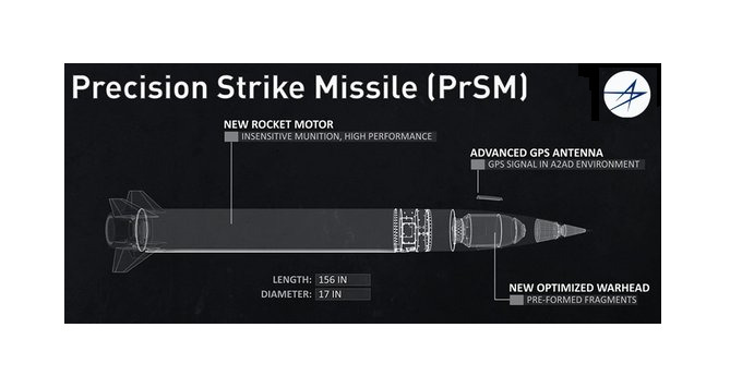
ATACMS is being replaced by the Precision Strike Missile (PrSM). It is HIMARS-compatible with two PrSM rounds in a pod. PrSM's old range was 499 km since the INF Treaty prohibited ranges ≥500 miles. The US withdrew from INF in 2019; now the range is potentially 800-1000 km.


Disclaimer: This is all public information from many sources. I'm no HIMARS expert and haven't even seen one in person. Much of this information is obsolete. I'm not revealing anything even slightly helpful to the Russians. Photo credits and other information are in the alt text.
Disclaimer: I want to avoid militaristic technology cheerleading. Even if the underlying technology is interesting, the fact remains that it is designed to kill people and blow things up (or at best provide deterrence). It would be better if this technology wasn't needed. 56/57
Disclaimer: It's important not to fall into the trap of thinking that technological wizardry and a new super-weapon will make all the difference. Even though providing tools is important, success primarily rests on the skill and bravery of the Ukrainian soldiers. 57/57
Most of the technical info is from "Ring laser gyro applications for tactical missiles: the Army TACMS solution" (1990) and "The International GMLRS Development Program" (2002). I'm not revealing anything new or secret; this was openly published in detail decades ago.
• • •
Missing some Tweet in this thread? You can try to
force a refresh