FlipperZero is an open source portable multi-tool: NFC/RFID reader/emulator, IR transceiver, sub-GHZ transceiver (CC1101 based) , SPI/UART tool, and much more.
It can even function as a U2F token!
More info here: flipperzero.one @flipper_zero #flipperzero
TinySA Ultra: small spectrum analyzer with a 4" screen, covering 100 KHz to 6 GHz. Also works as a signal generator. TinySA.org
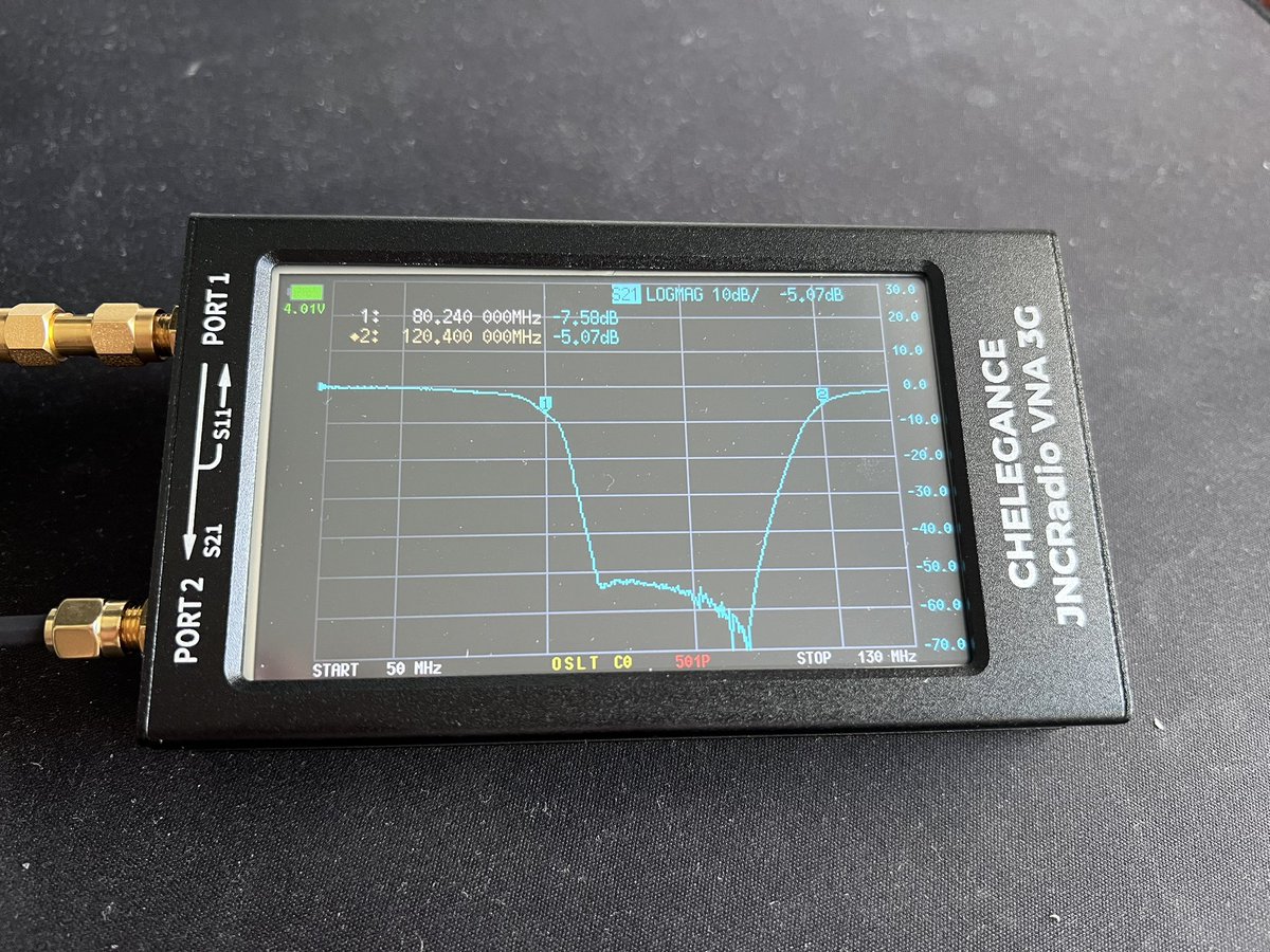
NanoVNA family: a portable VNA. Comes in different sizes, brands and prices. Mine covers 50 KHz to 3 GHz.
ERASynth Micro: open source signal generator covering 12 MHz to 6 GHz. Was crowd funded on @crowd_supply
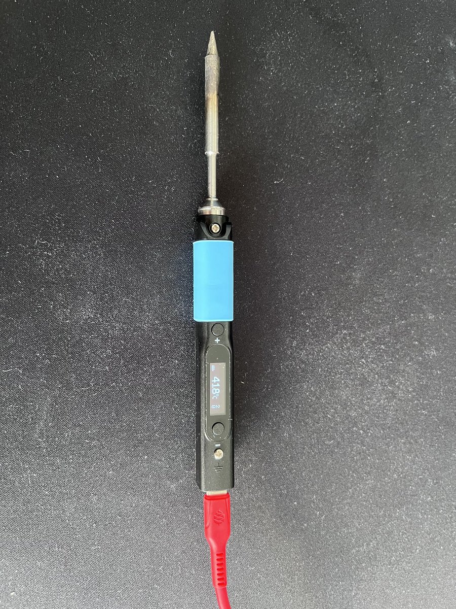
Pinecil: portable soldering iron. Can be powered by DC barrel jack or USB-C.
Made by @thepine64
I haven't used my Ersa station since I got this!
MEGO: portable power supply with built-in battery. Breadboard compatible. Outputs 4-24V.
Another product from Miniware: programmable & stackable DC power supply. The picture shows 3 products: MDP-P906 a 300W module in the bottom, MDP-P905 a 90W one in the middle, and MDP-M01 the control module on top.
They can also operate independently (without the control module)
Tigard: an open source multi protocol tool for hardware hacking designed by @securelyfitz
Supports UART, SWD, JTAG, SPI, I2C.
Portapack: add-on board for HackRF One to turn it into a portable SDR. Designed by @sharebrained
There are a few firmware options to choose from (I use mayhem)
RF Power Meter by ImmersionRC.
Can measure the calibrated frequencies: 35, 72, 433, 868, 915, 1200, 2400, 5600-6000 MHz
Runs on the internal battery and has an internal 30dB attenuator.
@newaetech's products. Depicted here: PhyWhisperer-USB: USB hacking device (sniffing, fuzzing, fault injection). ChipWhisperer Lite: side channel power analysis tool. PicoEMP: electromagnetic fault injection tool (ChipShouter's low-cost sibling)
PCBite by @SensePeek
A kit containing magnetic PCB holders and probes with compressible needles to help in hands-free measurements (using a multimeter, logic analyzer or oscilloscope on a device)
It's important to keep in mind that not all of these tools can compete with more professional alternatives (especially the measurement tools), however considering the price, I've found them very useful and accurate enough for hobbyist/DIY/amateur use cases.
End of the 🧵
• • •
Missing some Tweet in this thread? You can try to
force a refresh
🧵How to get into the RF world: a short thread for beginners.
As promised, here’s my tips to get into RF as a hobbyist/beginner.
Disclaimer: RF/Radio are my hobbies, but I'm not a professional RF engineer (My profession is “security”, and I studied computer science; I use RF/SDR for my job as well) so these tips may not be for you if you want to pursue it academically/professionally, or if you are already into RF.
1/8
Like any other hobby or field, you have to ask yourself what you want to achieve by getting into it.
If your goal is to get a PhD in communications, then this thread is not that useful. But if you want to learn to play with SDRs, get your ham radio license, build a hobbyist RF lab at home, learn wireless hacking, etc, then read on.
People who have “ham radio” or “RF” as a hobby, have very wide interests. Not everyone does the same. For example there are people who love receiving and listening to shortwave stations (even very distant ones) and they invest lots of time and money in their equipment. Some others like designing and building RF circuits like antennas and amplifiers. Some people are not RF experts, but use RF equipment (like SDRs or spectrum analyzers) in their job (example: using SDRs for wireless security and signal analysis, as part of security pen test).
I can go on and on with these examples, but my point is that you have to take parts of my advice that suit your goals/needs. And of course, this is my advice. Another person might have a totally different (and valid) approach.
2/8
One of the best ways to get into the RF world is to study for a ham radio exam, and get your license. Even if you never do any ham radio stuff, this is useful for 2 reasons: 1. You will learn a lot of useful RF basics, while studying for the exam (different frequency bands, antenna basics, signal propagation, regulations, basic measurements, etc) 2. After getting the license, you are allowed to legally transmit as well (whether you want to communicate with other amateurs or you want to do lab experiments, having a license is necessary/useful)
Here’s a thread on ham radio you can read for more details: 3/8
RF basics: Noise Figure.
A thread on the concept and measurement.
NF is a parameter to characterize how much a system (amplifier, receiver, mixer) adds noise to the signal, expressed as the degradation in signal/noise ratio as the signal passes through the device. 1/6
An ideal system (e.g. an ideal amplifier) will simply do what it’s supposed to do with the signal (e.g. amplify) without adding any noise, but in the real world, there are multiple sources of internal and external noise that will impact a signal.
In this thread I will not talk about other sources of noise (e.g. phase noise). I still have on my TODO list to write a detailed thread on phase noise.
The noise figure tells you the relative amount of noise being added to a signal as it travels through the system or device. We would like to ideally have this number as low as possible. Noise figure’s measurement unit is dB. When you buy an amplifier for example, you will see that noise figure is listed in the datasheet as one of the key parameters. If the amplifier is wideband, then usually a graph of noise figure across the whole bandwidth is provided.
2/6
Here’s an example screenshot from the datasheet of “Mini Circuits ZX60-123LPN+” which is a wideband amplifier (covering 50MHZ - 10GHZ). I will measure the noise figure, and compare my measurement to the datasheet to see if my unit performs according to the specs.
An introduction to Software Defined Radios.
A thread for beginners on: 1. What a SDR is 2. What you can do with SDRs 3. How it plays a role in the security/hacking world 4. How it’s used in ham radio. 5. How to choose/buy one 6. Link to more reading material
0/21
Disclaimer: I need to oversimplify many concepts, and also omit/skip some advanced ones. This is a huge topic that can’t be covered in a few posts, and my target audience is beginners.
What is SDR? If you’ve heard of RTL-SDR or HackRF but aren’t sure why they’re so popular among hackers, ham radio enthusiasts, and the SIGINT community, this thread is for you.
Traditionally, radios were fixed-function, and all implemented in hardware. An FM radio did just that: receive FM in the 88-108 MHz range. If you wanted to listen to let’s say shortwave (3-30MHZ), then you needed a new radio that had that functionality. You were limited to the hardware.
SDRs change this. With SDR, the hardware is controlled by software, giving you flexibility. Basically, many functions that traditionally were done in electronics circuits (e.g. filtering, demodulation, etc) are done digitally in SDRs.
Want to listen to FM? Easy. Want to explore Bluetooth or decode satellite downlink? Same device, just different software, or different settings in your SDR app. You define the functionality in software (e.g. which frequency to dial to, which modulation to use to demodulate the signals, what bandwidth to use to receive the signal, etc). Think of it like this: all the physical knobs that you had in the older radios, are now replaced with UI elements in software.
1/21
This brings up a world of possibilities: you could prototype systems in software, that were only possible to be made in hardware in the past. You can use the same SDR that is used to listen to FM radio, to sniff modern wireless protocols (e.g. Bluetooth). This hugely shortens the time to implement a new proof of concept for many use cases (production, research, idea validation, testing etc), and also saves you hardware cost, as most of your time would be spent in software (assuming that you’re using a commercial SDR, already built by another company, like what we cover in this thread)
🧵 RF basics: Power meter.
A short thread for beginners.
If you need to measure a radio signal’s power precisely, you need an RF power meter.
It basically shows the signal’s power in dBm (or milliwatts)
In this thread I will introduce the different types, with examples. 1/7
First of all, why do we need to measure a signal’s power with a power meter, if we can “see” the signal on the spectrum analyzer, which also shows the amplitude?
Well, there are many reasons. One of them is that spectrum analyzers are not as accurate as power meters when it comes to power measurements (we’re talking ~±1dB vs ~±0.2dB. This is important in some use cases like testing transmitters, regulatory compliance, etc). Power meters are also much more accurate for complex wideband signals (e.g. LTE). And, power meters/sensors can be calibrated against some standards. Not to mention the cost! For example a 26GHz spectrum analyzer is much more expensive than a 26GHz power sensor.
But why do we need to measure power at all? Apart from the above reasons, we need to make sure every component or circuit either receives the required power at its input, or generates output in the desired range, or both.
Although the unit for power is Watt (W), in the RF world it’s measured and described in dBm (dB relative to 1 milliwatt)
2/7
A simple definition, to avoid confusion: power sensors are the devices actually measuring the power. Power meter is the device that shows the measured value. Now, as you will see below, sometimes these 2 are sold as one integrated device, and sometimes they’re separate. (now that you know the distinction, I will use them interchangeably in the text)
Power meters/sensors can be categorized based on 3 features or parameters: 1. USB-based or stand-alone:
Some power meters are stand-alone (like the small immersionRC in the picture). It doesn’t need a computer to work. Some are USB-based, like the Anritsu shown in the picture. You need to use the accompanying software from the vendor. 2. Internal or external sensor:
Some power meters need an external power sensor to work. It’s like the power meter is the “interface” that can connect to different types of sensors. The 2 Agilent sensors you see in the picture, are sensors. They can only be connected to specific Agilent/Keysight power meters, and work with them.
Some power meters can work with both their internal sensor, and also accept external sensors (like the GenComm) 3. Average/CW vs Peak vs True RMS:
Depending on your use case or the signal you want to measure, you need to use the proper power sensor. To measure a simple unmodulated signal, you can simply use a CW/average sensor. An RMS sensor is better suited to measure complex or modulated signals. A Peak sensor can also measure the short bursts (which can’t be done by the other sensors), like pulsed RF or radar.
(we can also categorize based on the detection mechanism, like diodes or thermocouples, but I will skip that)
3/7
🧵 RF basics: mixers.
A thread for beginners on: 1. What an RF mixer does 2. Understand its datasheet 3. Test its specs
I've picked Mini Circuits ZMDB-24H-K+ for this thread to work on.
1/7
As the name suggests, mixers are used to “mix” signals. But what does “mix” mean in this context?
Mixers have 2 input ports , and an output port.
When you “mix” 2 signals, you end up with multiple signals at the output!
f_out = |f_RF ± f_LO|
So, you have the sum and also difference of the signals!
The output is usually called IF (intermediate frequency)
The main input is called RF (radio frequency)
And the other input that basically controls what happens to RF is called LO (local oscillator)
You can use LO to down-convert RF.
A very practical example is down-converting a multi-GHZ signal down to less than 6GHZ so you can “see” it with your typical 6GHZ spectrum analyzer or SDR.
So, when you hear the terms “down-converter” or “up-converter”, you know they’re simply mixers inside.
[note: in this thread I am treating the mixer as down-converter. Mixers can also work in the other direction (IF to RF) as shown in this screenshot, and work as upconverter. Mixers are bi-directional devices]
2/7
Now, let’s look at the main specs of a mixer:
A very important spec is the RF frequency range. In our example it’s 5-21 GHZ. Then the IF bandwidth is important which in our case is DC to 5 GHZ. This means we can translate or convert any signal from 5-21GHZ, to 0-5GHZ, as a down-converter.
Conversion loss: it’s a very important spec and refers to the reduction in signal power from input port due to the mixing process. Lower losses are desirable.
L-R and L-I isolation: naturally we don’t want the LO to leak into the output. So the higher this isolation the better.
Level 15: our mixer is level 15. This means we need to provide a 15dBm signal to the LO port. There are other levels as well (e.g. 7 or 10)
🧵 RF basics: Attenuators.
A thread for beginners on: 1. What an attenuator does 2. Different types of attenuators 3. Understand the datasheet terms 4. Test its specs
1/4
An attenuator is a passive component that “attenuates” a signal’s amplitude, ideally not impacting its other parameters like frequency. Let’s say you have a 0dBm signal and connect it to an attenuator , and let’s say your attenuator is 20dB. In this case, you’re going to get a -20dBm signal after attenuation. It may not be exactly 20dB of attenuation, because attenuators like any other component or circuit, have some tolerance (let’s say +-0.5dB)
Most attenuators are bi-drectional, so it doesn’t matter which side of it you use as input or output.
Generally we can say we have 2 categories of attenuators: fixed and variable. Fixed is fixed: 1dB, 5dB, 20dB, etc. On a variable attenuator, you can change the amount of attenuation either manually (like physically with a knob/selector, as you can see with HP in the picture on the previous post) or programmatically/digitally (as seen in this diagram from Mini Circuits)
2/4
What are the most important specs of an attenuator? 1. Obviously the attenuation is the first: for a fixed attenuator, it would be just a number in dB (e.g. 20dB). For variable attenuator, it would be a range (e.g. 1-10dB, or 10-100dB) 2. Frequency range: the frequencies that you can attenuate the signal and expect the attenuator to do its job according to the datasheet (e.g. DC-6GHZ) 3. Power handling: how much power the attenuator can safely dissipate (e.g. 2W, 20W, …). Usually a high power attenuator is bigger and heavier because of heat sinks used. 4. VSWR: it’s a ratio describing impedance mismatch. A lower VSWR means better impedance matching , minimizing signal reflections.
Here’s a fixed attenuator from @MiniCircuits , and its datasheet