It's time for science fiction. The 2nd of 3 radical aerospace design concepts we'll focus on, let's look at the Blended Wing-Body (BWB) aircraft, and Boundary Layer Ingestion.
Pegasus or White Elephant? Read on.
Pegasus or White Elephant? Read on.

Efficiency. It's the pursuit of the impossible, of perfection. Closer and closer to zero we get, by narrower & narrower margins, to kiss the surface of infinity.
And that's what we will need in the decades to come. So, the blended wing...
And that's what we will need in the decades to come. So, the blended wing...

Compared to conventional airframes, the blended wing-body allows a near perfect elliptical lift distribution, a far more even weight distribution and a profile that more nearly matches the area rule: So, reduced induced drag, reduced weight and reduced wave drag in one.

In 1998 the AIAA published a concept for a long range blended wing design to the scale of the A380 Superjumbo. A monster, 280ft wide with two decks carrying up to 800 passengers 7000 miles, it was modelled to have a fuel burn 30% lower than a conventional Superjumbo aircraft.


But that extreme scale is a narrow niche, which is why the A380 itself was a commercial failure. The biggest target for BWB aircraft is the crucial small-medium range market, sub 2000km and competing with 737s and A320s.

The trouble is that at these shorter ranges, the fuel efficiency benefit for the BWB collapses down to 10%-15% over conventional aircraft: Not sufficient to withstand massive airframe development risk.
So what do we do to prevent it being relegated to a long range niche only?
So what do we do to prevent it being relegated to a long range niche only?

Remember that simpler Truss Braced designs, if allowed extra wingspan, can manage a 7%-10% benefit, plus dovetail with transonic Natural Laminar Flow (NLF) wings, unlike BWBs. All of this stacks the odds against short/ medium range BWBs, except...
https://twitter.com/Jordan_W_Taylor/status/1667099074842046465?t=EJ4QkGVHfTjHGHs3M6QHvw&s=19
Two things.
Firstly, the vast internal volume of the BWB makes it a good candidate for novel, clean but volume intensive fuels such as hydrogen, if the market moves that way.
Firstly, the vast internal volume of the BWB makes it a good candidate for novel, clean but volume intensive fuels such as hydrogen, if the market moves that way.

Secondly, BWB designs are an excellent platform for novel engine integration, allowing Boundary Layer Ingestion (BLI).
What is BLI?
What is BLI?

BLI uses a carefully placed engine to suck boundary layer air, reducing engine ram drag and energising the upstream boundary layer simultaneously. A carefully chosen body/ engine combination reduces drag by another 5%-10%.
But blended wing/ body BLI is not well understood.
But blended wing/ body BLI is not well understood.


For example in this simulation a poorly positioned engine's backwash is causing flow separation over the rear of the aerofoil, with significant drag and control implications.

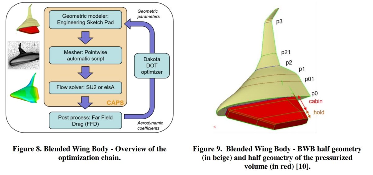
NASA investigated BWB BLI in 2000, but recently ONERA did the same on the small-medium range scale using powerful CFD optimizers: First they took their A320 scale BWB linked below and further cruise optimized it, raising L/D another 6%...
https://twitter.com/Jordan_W_Taylor/status/1664565089049931779?t=0ofKgc-eC_AZyzLytuGMxg&s=19
Then before investigating BLI, trim optimization was needed: Since the BWB body functions as a main wing, it needs to be at a slight angle of attack during cruise. Optimizing this for cruise means smaller elevon trim settings.
Static pitch stability was also confirmed.
Static pitch stability was also confirmed.

Four engine integration concepts were studied: Two wing mounts, one with a large S duct, one rear mount and one rectangular nacelle. All are close to the wing: When ducting impinges cabin space, you are restrained: Moving the engine up creates the induced separation issue shown.


Development and extreme care is needed in positioning: Corner separation in 1 is resolved in 2, but compromises with a large S duct. 3 is cleanest of all but compromises on structure and takeoff/ landing rotation.
All must allow for induced vibration in the engine fan stage.
All must allow for induced vibration in the engine fan stage.

So the setup has promise and huge efficiency potential, even for small/ medium range and within a 36m span limit, but much needs to be addressed: Low maintenance engine integration and integration of high lift devices is one challenge.

Optimal non cylindrical pressurised fuselage sections are another, but CFRPs have so thoroughly replaced Aluminium already in airframes that this, at least, is a smaller challenge than it once was. Still, the optimal setup remains unknown.


The biggest stumbling block is probably risk appetite for the big airframers: Why risk developing something so revolutionary and difficult? Planes are hard enough already, and a truss-braced high AR wing with an efficient high bypass engine gets you partway with less risk.

Personally, I think fuel choice will be the decider: High volume non-kerosene fuels like hydrogen would open the door to the BWB. It needs a step change of that magnitude.
Nobody knows what a low carbon economy looks like, but in aviation at least it might look like this.
Nobody knows what a low carbon economy looks like, but in aviation at least it might look like this.

Publications used for the thread are shown. Hope you enjoyed this!


Our 3rd and final entry for novel high efficiency concepts will be Distributed Hybrid Propulsion. Stay tuned...

• • •
Missing some Tweet in this thread? You can try to
force a refresh