🧵regarding the comparative ability of different parts of a Blake surgical drain to actually drain fluid.
Here I've used an ice cube tray model to explore whether the different parts of the drain act the same.
We will also explore some properties of the Blake as we go.
(1/ )

Here I've used an ice cube tray model to explore whether the different parts of the drain act the same.
We will also explore some properties of the Blake as we go.
(1/ )


Before the experiment, some basics.
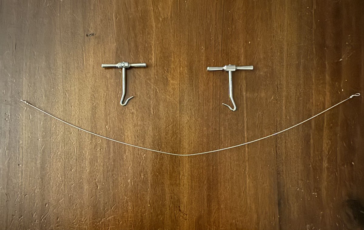
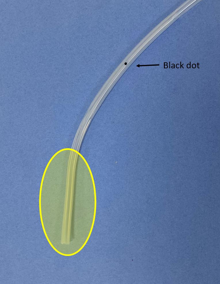
The Blake drain has 3 parts:
- the 'fluted' part, which is the part that actually drains
- the drain tubing that connects to the bulb
and
- the 'transitional part' between them. The black dot is here. We will look at this in more detail.
The Blake drain has 3 parts:
- the 'fluted' part, which is the part that actually drains
- the drain tubing that connects to the bulb
and
- the 'transitional part' between them. The black dot is here. We will look at this in more detail.

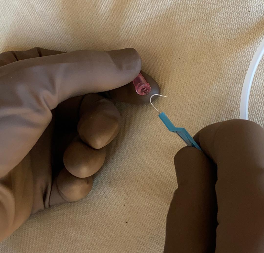
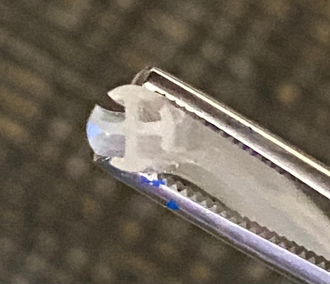
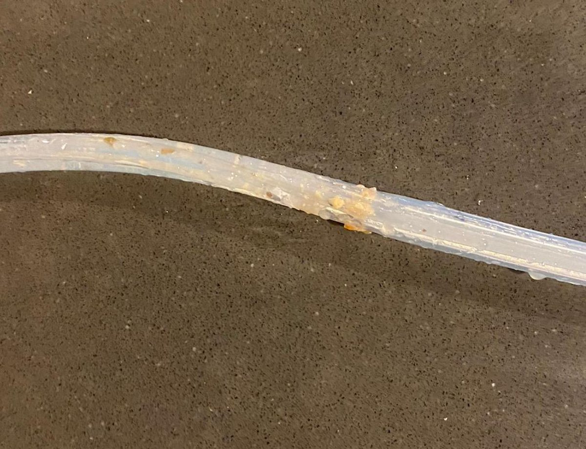
Here's what the different parts look like in cross section.
The fluted part basically has 4 channels which are separate. This will be important later.
The 'transitional' part still has 4 channels. It is noticeably stiffer than the 'tubing' section, which has only one channel.
The fluted part basically has 4 channels which are separate. This will be important later.
The 'transitional' part still has 4 channels. It is noticeably stiffer than the 'tubing' section, which has only one channel.

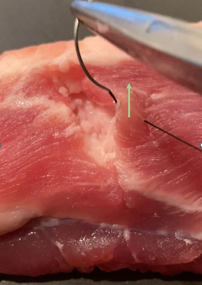
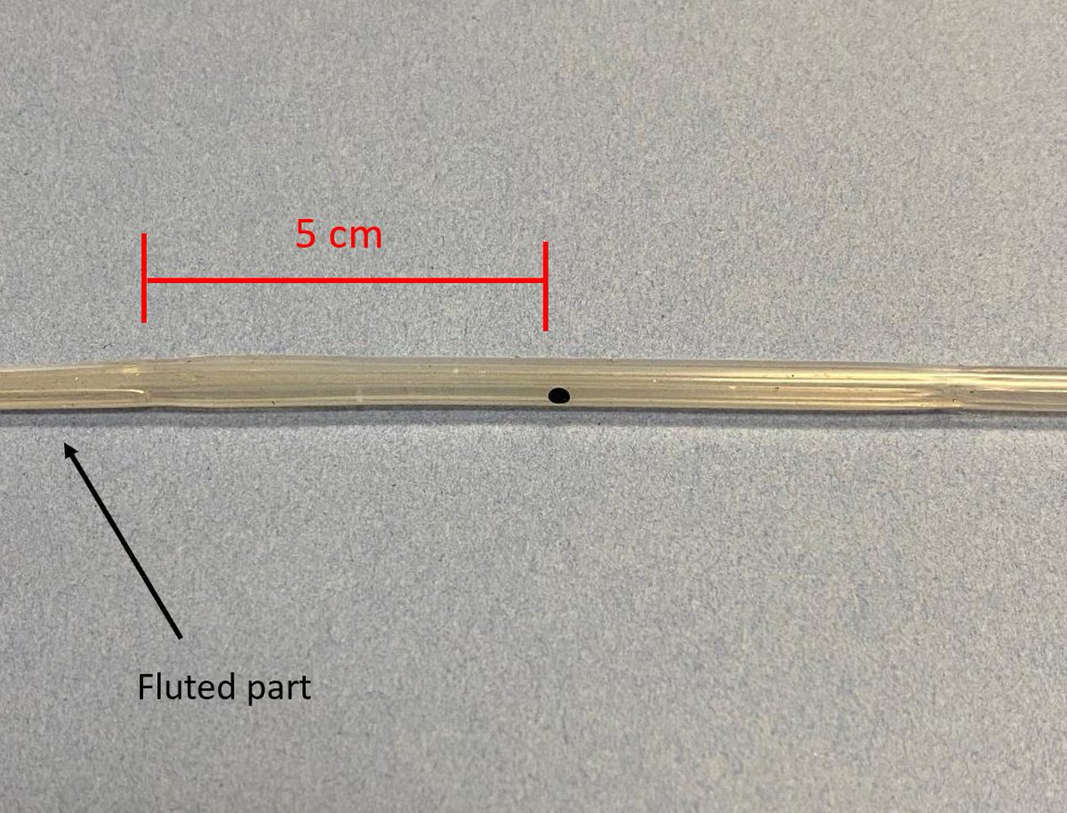
Note that there is a 5 cm distance from the black dot to the fluted (functional) part of the drain.
This means that the black dot can be visible externally, but so long as the fluted part still remains internal, the drain will still function.
This means that the black dot can be visible externally, but so long as the fluted part still remains internal, the drain will still function.
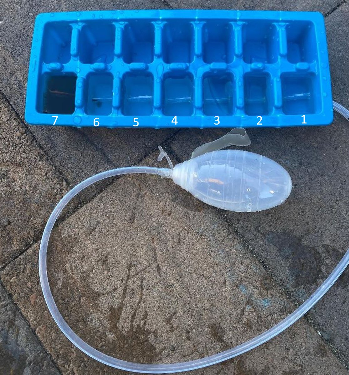
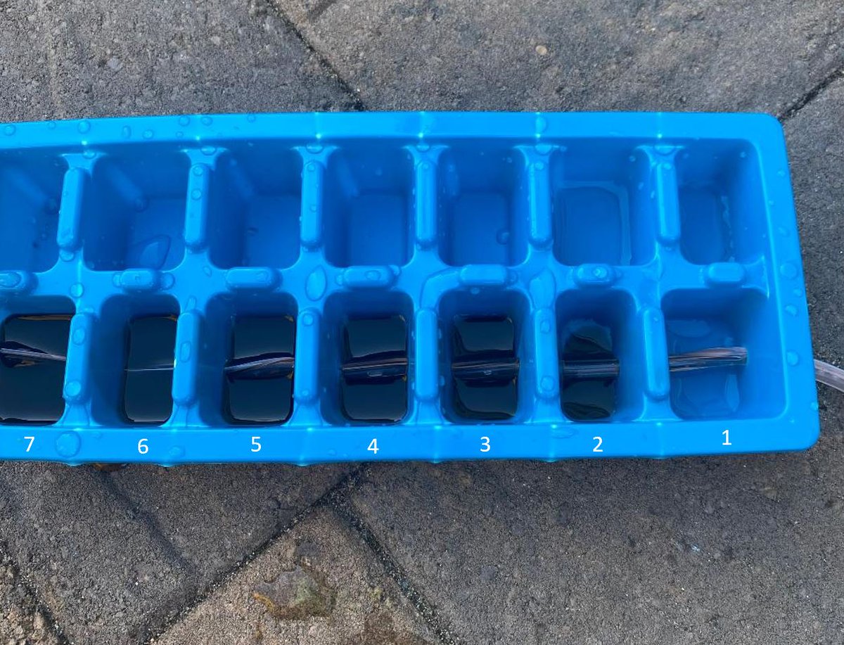
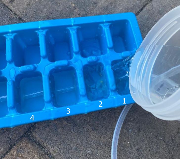
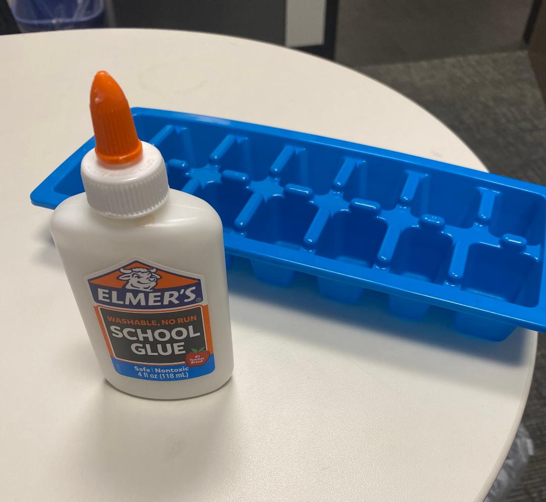
Now for the model:
I hypothesized that the more proximal portion of the drain (1-2) would work better (have better suction) than the distal portion (6-7).
The seal in between sections was maintained with the help of tape and Elmer's glue, and then adding Play-Doh.
I hypothesized that the more proximal portion of the drain (1-2) would work better (have better suction) than the distal portion (6-7).
The seal in between sections was maintained with the help of tape and Elmer's glue, and then adding Play-Doh.
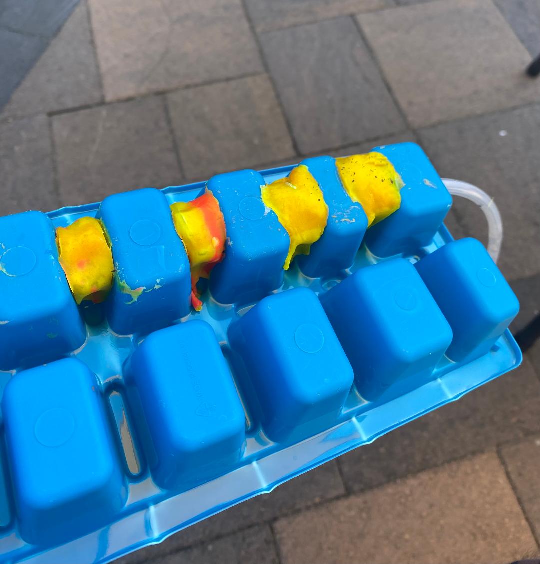
Now the suction has been activated.
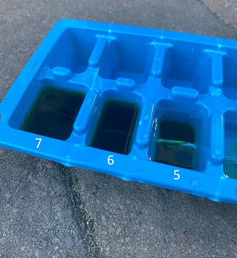
The *initial* results were as I expected. The proximal compartments (1-3) drained first and drained the most, with the distal compartments (6-7) barely drained.
Still, there has been *some* drainage, as evidenced by the brown dye diffusing.
The *initial* results were as I expected. The proximal compartments (1-3) drained first and drained the most, with the distal compartments (6-7) barely drained.
Still, there has been *some* drainage, as evidenced by the brown dye diffusing.
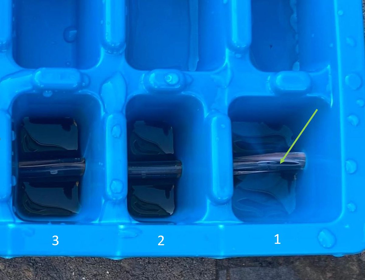
Initially, I had thought the drain might stop working altogether once it became exposed to air in the proximal-most compartment (#1).
And indeed it did start entraining air, but the drain still kept working, though slower.
And indeed it did start entraining air, but the drain still kept working, though slower.
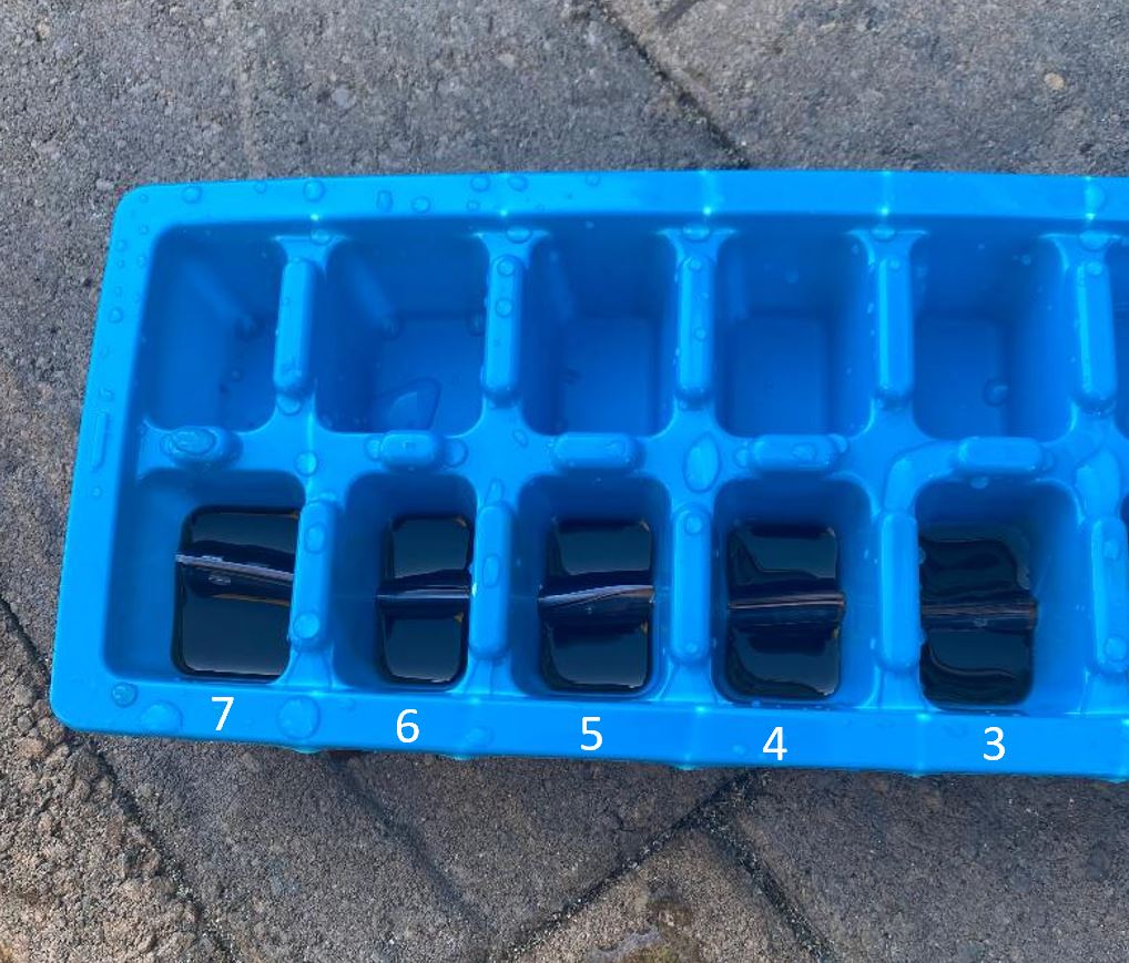
At this point, the distal compartments started draining, even when all were exposed to the air.
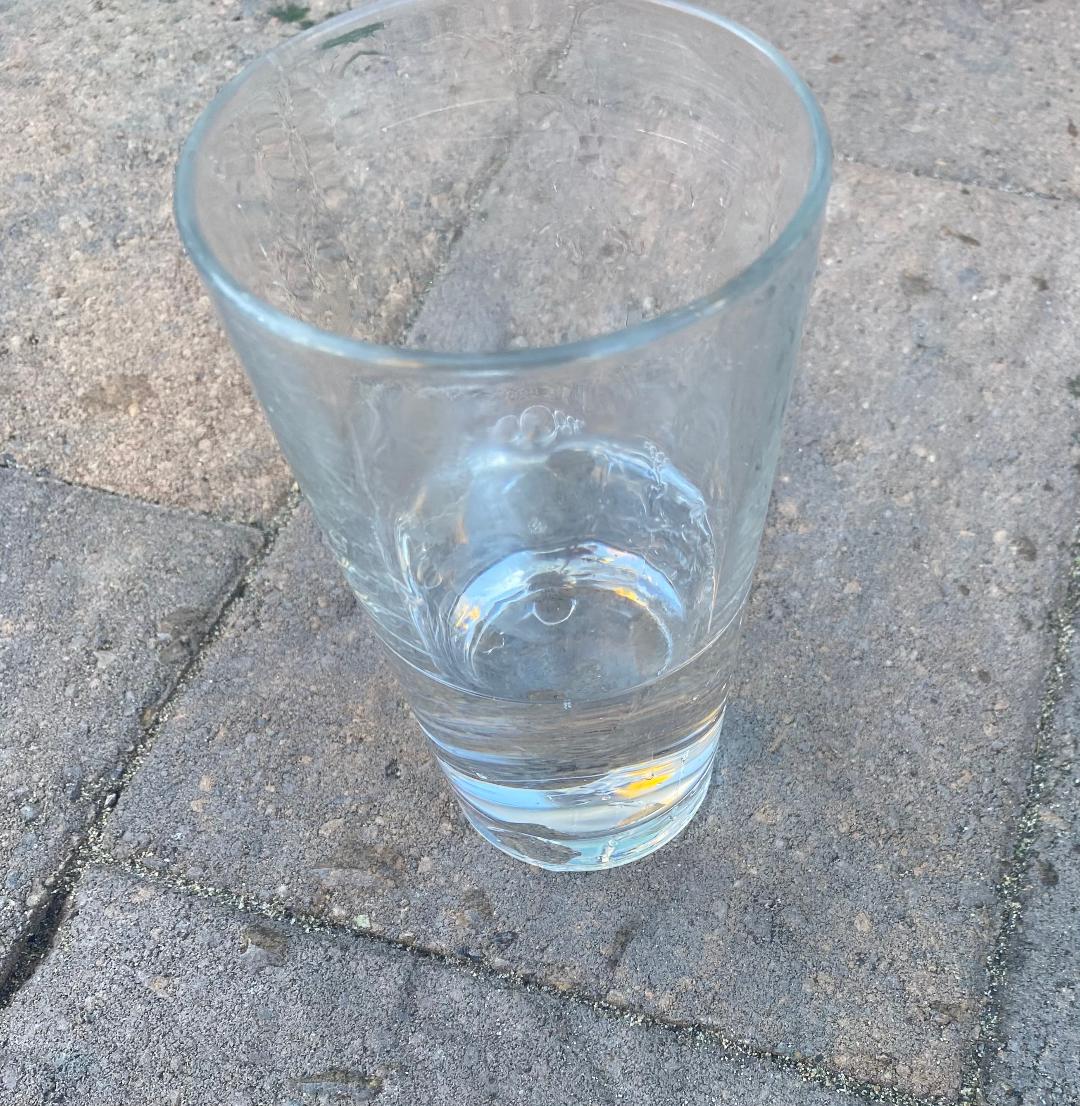
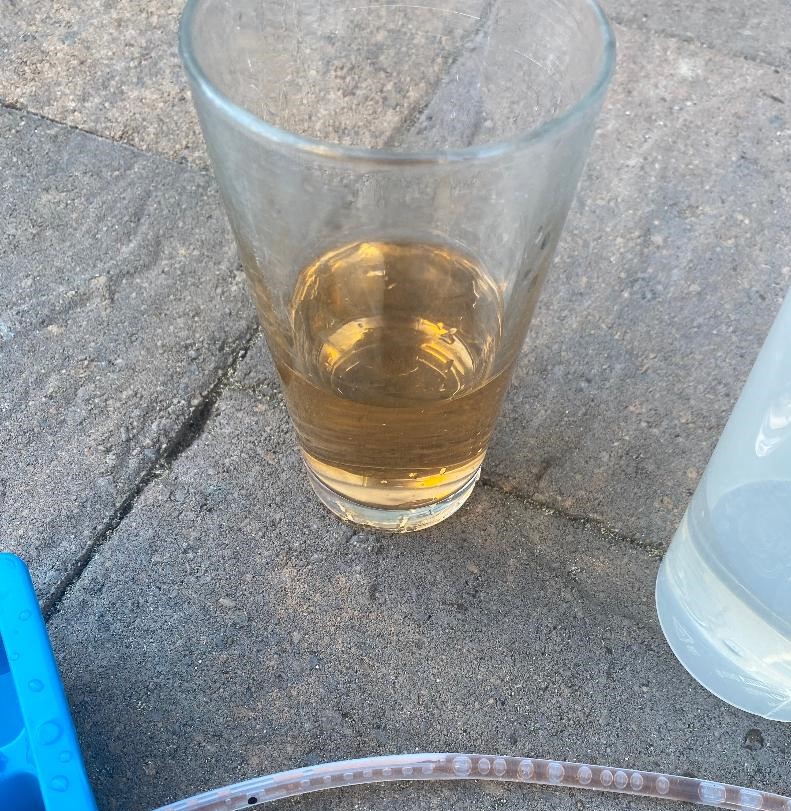
The fluid salvaged from the bulb at first was clear, but later on, it started becoming brown-tinged (R pictures).
The fluid salvaged from the bulb at first was clear, but later on, it started becoming brown-tinged (R pictures).
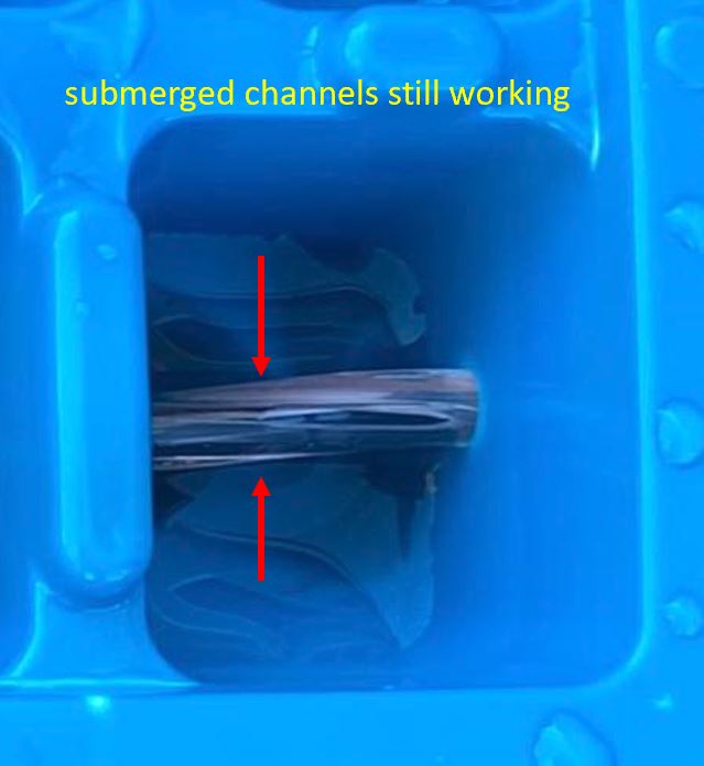
The drain kept working despite one of the channels being exposed because of the design of the Blake:
It has 4 channels that are separated from each other...essentially it is 4 drains that happen to be all in the same tube. The channels that were submerged were still working.
It has 4 channels that are separated from each other...essentially it is 4 drains that happen to be all in the same tube. The channels that were submerged were still working.
Now for the important part:
I then tried keeping the proximal compartments filled all the time, *so that they were never allowed to fully evacuate*.
The proximal boxes kept draining, but the distal boxes were drained only slightly, and most of the dye remained here.
I then tried keeping the proximal compartments filled all the time, *so that they were never allowed to fully evacuate*.
The proximal boxes kept draining, but the distal boxes were drained only slightly, and most of the dye remained here.
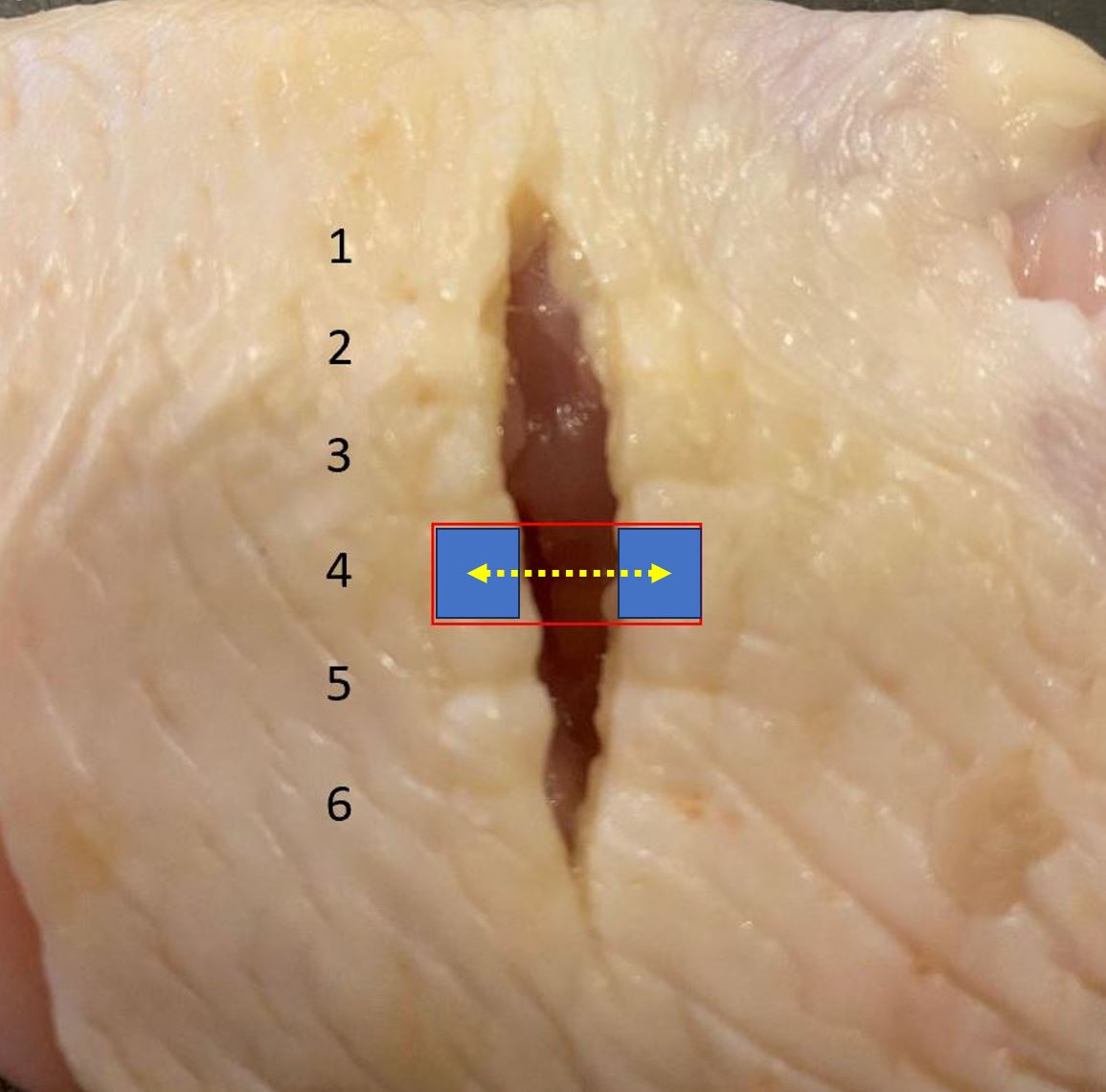
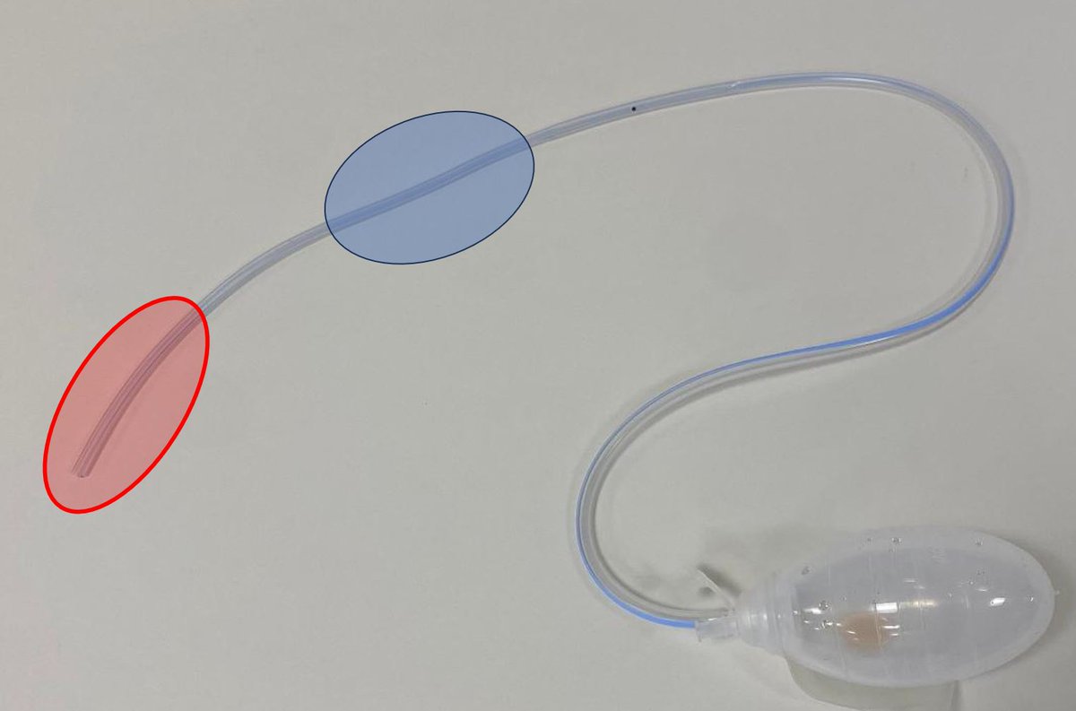
This is probably the most important concept in the 🧵.
The drain's behavior is such that if the proximal area (blue) is in an area where it has a steady output, then most of the drainage will occur here...and the distal (red) area may not drain well (or perhaps not at all).
The drain's behavior is such that if the proximal area (blue) is in an area where it has a steady output, then most of the drainage will occur here...and the distal (red) area may not drain well (or perhaps not at all).
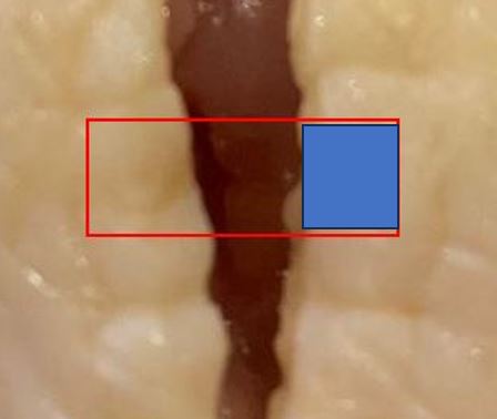
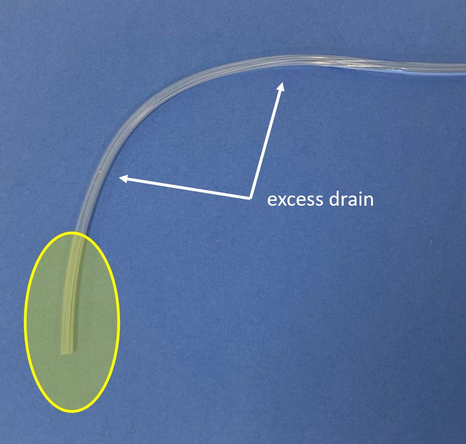
Generally speaking it is best to avoid having too much excess drain tubing, *especially proximally* where it is most effective.
In the L picture, the area of interest (yellow) is small, and there is a lot of excess tubing. On the R the drain is trimmed to a more suitable length.
In the L picture, the area of interest (yellow) is small, and there is a lot of excess tubing. On the R the drain is trimmed to a more suitable length.
It is also worth noting that if the proximal portion of the drain gets clogged with debris, then the drain will be entirely nonfunctional, as I showed in the 'salad dressing' experiment from a year ago (link below).
x.com/rbarbosa91/sta…
x.com/rbarbosa91/sta…
Limitations of the study include the fact that ice cube trays may not act exactly like the human body.
Ice cube trays were obtained from the Dollar Store (Beaverton, OR). Elmer's glue was obtained from Target (Beaverton, OR). Play-Doh was borrowed from Henry.
⬛️
Ice cube trays were obtained from the Dollar Store (Beaverton, OR). Elmer's glue was obtained from Target (Beaverton, OR). Play-Doh was borrowed from Henry.
⬛️
• • •
Missing some Tweet in this thread? You can try to
force a refresh