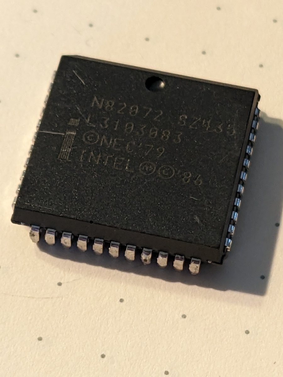
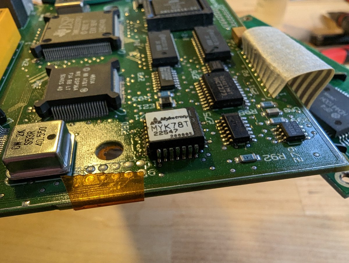
A while back, @david_rysk asked me to dump the firmware of the Wersi SL-M2 51173 Slave Sound Generator, a plugin module for Wersi's DX10 synthesizer. @p4ula sent me three boards from Germany, and this thread will show the extraction process from the saw to the bits. 1/n 

The Z8 chips are known to have a diffusion ROM, but I don't want to waste HNO3 dissolving the whole package. Instead, I used a bandsaw and a handy PCB jig to saw out the center. Soldered legs keep it from flying off. 2/n


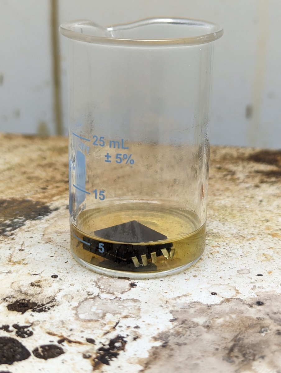
After sawing, the center of the package fits in a 25ml beaker. I bent the legs to keep the package just a smidge above the beaker's floor, then added just enough red fuming nitric acid to submerge it. 3/n 

A bit of heat causes the acid to happily tear apart the package. Play this video on mute if you'd rather not year the inside of my fume hood. 4/n
RFNA leaves behind the pins, bond wires and frame. I pluck the bond wires off with tweezers, and the frame is easily removed by 20% HNO3 and a little heat.
(H2O helps HNO3 attack metal, so weak acid destroys the frame that strong acid leaves behind.) 5/n


(H2O helps HNO3 attack metal, so weak acid destroys the frame that strong acid leaves behind.) 5/n


Quick pause in the thread while I move from my phone to my desktop. Here's a lazy dog to look at while you wait. 6/n 

Now that the chip is open and the frame removed, I can begin photographing the surface. This is done as a number of still images that are later stitched together with Hugin and Pantools.
Here you can see three shots on the left of the chip, from minimum magnification. 7/n


Here you can see three shots on the left of the chip, from minimum magnification. 7/n


Having reverse engineered other Z8 chips, I know that the giant structure in the west is the ROM, with the microcode in noth and RAM in the center south.
No bits are visible yet, for that we'll need delayering.
9/n
No bits are visible yet, for that we'll need delayering.
9/n

Here's the Zilog surface logo, by the way, where 8611 refers to the Z8611 prefix of the part number. 10/n 

And here are bits of the ROM as best they can be seen from the surface. You can't read them, but sometimes at the right distance, you can get a feel for how dense the ones are. Better to save that frustration and delayer. 11/n 

Delayering is performed by a quick bath in dilute hydrofluoric acid. This must be done in a plastic beaker, as HF will etch a glass beaker.
After delayering, the surface changes drastically. With the mess of wires gone, organs of the chip now stand out from eachother. 12/n
After delayering, the surface changes drastically. With the mess of wires gone, organs of the chip now stand out from eachother. 12/n

This photo of the ROM holds all the bits of the program. There's a lot left to do, but now we know that it will work! 13/n 

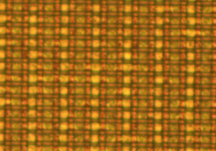
Within that image, bits come in pairs of two rows. Wherever the diffusion layer passes under the horizontal wire, we have a working transistor or a One. Wherever there is no diffusion blob stretching beneath the wire, we have a broken transistor or a Zero. 14/n 

Here's a bit less zoom. With pen and paper, you should be able to write down the bits of the first row:
10100011101110011011001111
15/n
10100011101110011011001111
15/n

While it is possible to type in all of the bits, I'd lose my mind or my patience in the process. Instead, let's use MaskRomTool to extract the bits by first making row and column lines that match the bit placement. 16/n 

After marking the first hundred bits, I can choose a color threshold and sampling strategy to recognize their values. Here, I get complete separation in both red and green when sampling the darkest color of a 12-pixel wide stretch. 17/n 

If you'd like to try this yourself, prebuilt binaries of MaskRomTool for Mac and Windows and a tutorial of extracting the ROM from a GameBoy CPU are both on Github. 18/n
github.com/travisgoodspee…
github.com/travisgoodspee…
Taking a break from the thread for coffee and steak. I'll finish the markup after lunch and toss the bits on github.
This is Chili. He's a damned fine cat if you avoid the sharp parts. 19/n
This is Chili. He's a damned fine cat if you avoid the sharp parts. 19/n

• • •
Missing some Tweet in this thread? You can try to
force a refresh

 Read on Twitter


