The US Navy, like the US Air Force, wanted a better solution for bomber interception after the end of the Second World War.
The engineers at Naval Ordnance Test Station China Lake came up with a low-cost, simple, and highly reliable missile. The Sidewinder. 🧵
The engineers at Naval Ordnance Test Station China Lake came up with a low-cost, simple, and highly reliable missile. The Sidewinder. 🧵

A short admin note. I'm going to start by explaining the function of 9A/B, then do my best to track the changes between 9B to 9D, then cover the combat record of 9B and 9D, the development of SEAM and 9G/H, and maybe on to 9L. These different stages will be different threads.
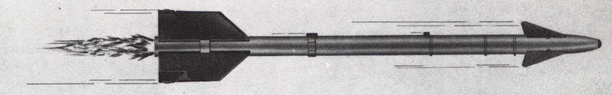
First, AIM-9A/Sidewinder 1/Sidewinder Mk. 2 Mod 0. This version of the Sidewinder was mostly used for initial operational testing and evaluation, but the basics of Sidewinder guidance were pioneered here. (Two pictures are supplied because AIM-9A descriptions & depictions vary)


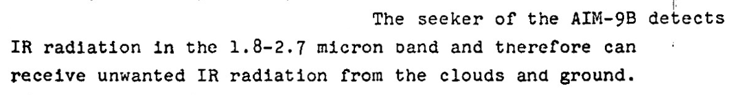
To explain the guidance loop, you need to know how the missile sees the target. The detector material used in the rear-aspect AIM-9s is Lead Sulfide, or PbS. When uncooled, it is sensitive in short-wave infrared. In SWIR, exhaust plumes are invisible, and engine metal is visible.
Now for the guidance system. These early Sidewinders used something called amplitude modulation. That reticle spins at a given rate set by the gyroscope-telescope assembly.
The logic here aims to turn the modulation waveform to zero. To do that, the target should be centered in the reticle, meaning that the transmission is 50% overall.
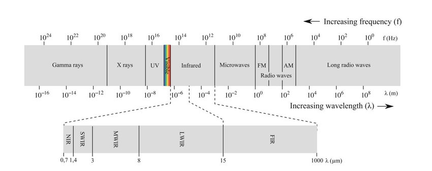
This is the reticle shared between AIM-9A and 9B, covering a 4° FOV. The checkering pattern significantly improves the rejection of false IR targets, such as clouds. Those produce a constant DC signal, like in the 50% coverage portion, and therefore are easier to filter out.
This reticle spins at 70hz, since the reticle is fixed to the telescope-gyro assembly.
This is a basic block chart of AIM-9A's guidance and control section(GCS) and a description of how the seeker gyro produces steering commands. The commands that keep the gyro and the reticle centered also provide proportional steering commands.
As the spinning reticle generates signals that keep the gyro centered on the target, these signals also move the canards to bring the missile into an intercept path. The angle between the sight line and the flight line remains constant, bringing the missile into the target.
This guidance system is so simple because it does not require a separate guidance input for roll stabilization, like other missiles of the time did (the AIM-4, for example). This was made possible by some genius, who developed the rolleron.

As an aside, this is a Soviet R-3S. This appears to have the same rear fin and rolleron arrangement as the early Sidewinder 1A(9B).
Taiwan was likely supplied with very early Mk 17 Mod 1 motors, which had these horizontally hinged rolleron mounts.
Taiwan was likely supplied with very early Mk 17 Mod 1 motors, which had these horizontally hinged rolleron mounts.
The rolleron is a notched metal wheel on a tab that spins in the airstream, creating a gyroscope. The missile has a tendency to roll for many reasons. As it tries to roll, these gyroscopes want to stay stationary, so they pivot the tabs in a direction that counteracts the roll.
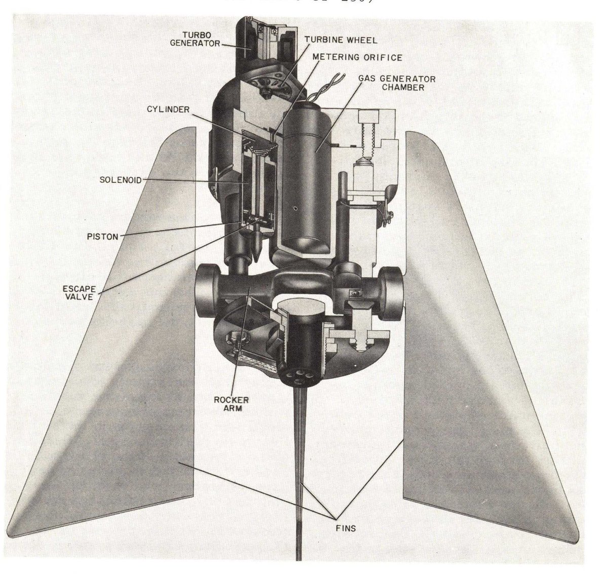
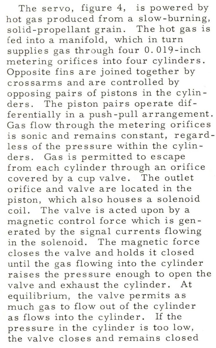
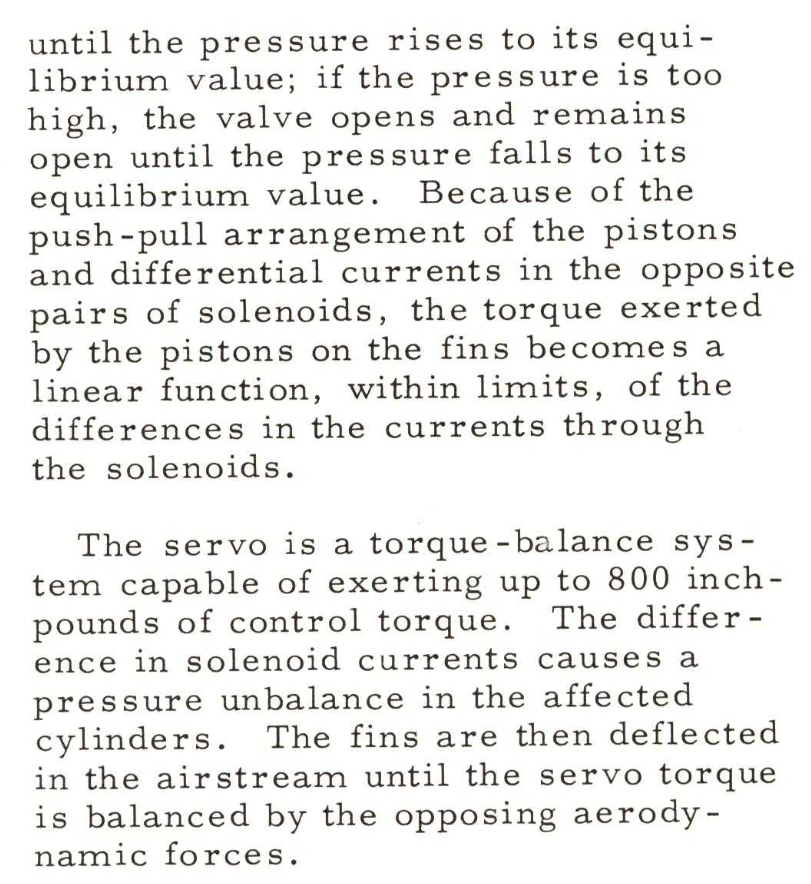
This section details the incredibly simple gas system and turbo-generator used to power the missile in flight and provide steering force to the fins.
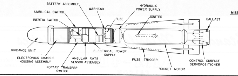
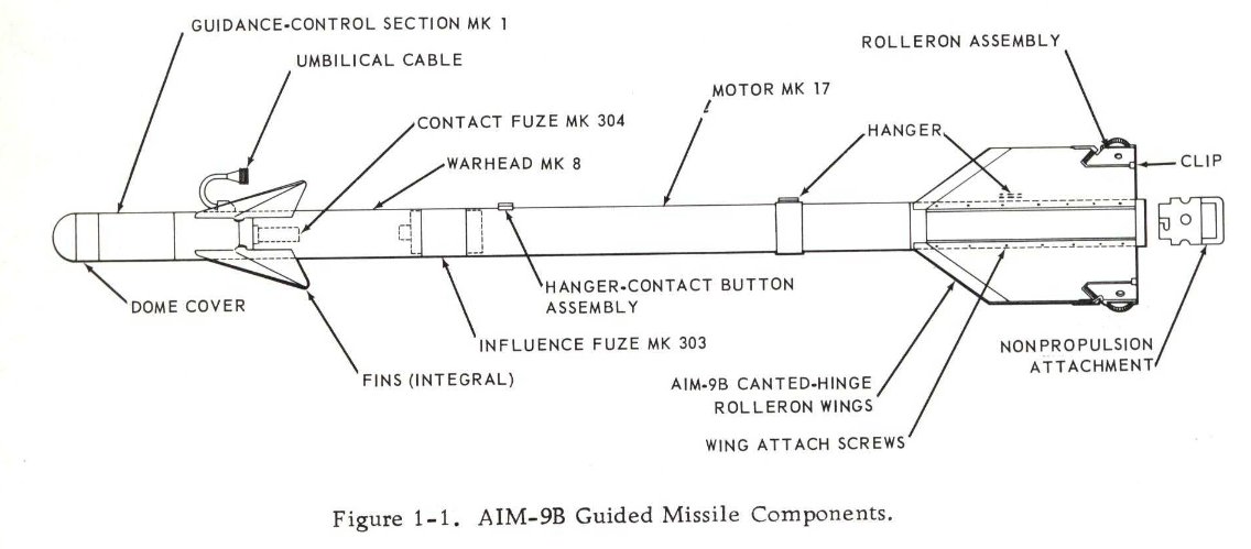
These features were all present on the AIM-9A, and were carried over to the 9B(Sidewinder 1A/Mk. 2 Mod(s) 1-14). The biggest changes between 9A and 9B were the improved contact fuze, improved seeker, and angled fins of the Mk 17 motor as compared to the straight-finned Mk 15.
The rollerons were changed from horizontal hinge to angled hinge with Mk 17 Mod 3 and up. This was limited to usage with the Guidance and Control Sections Mk 1 Mod 1, or the 9B GCS.
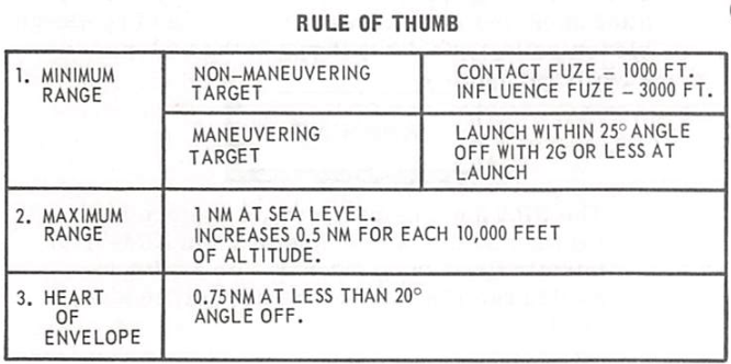
Working rearward on the missile, next is the contact fuze. In AIM-9A, this was a set of wires, that when broken on impact, would short to ground and trigger the warhead. In AIM-9B, it was a set of barium titanate crystals that would generate electricity on impact.
The warhead was a 25-pound blast-frag unit with 1,300 pre-formed square fragments.
Behind the warhead was the Mk. 303 influence fuze. This was an IR-based unit, working in the same IR band as the seeker.
Finally, in the back was the rocket motor.
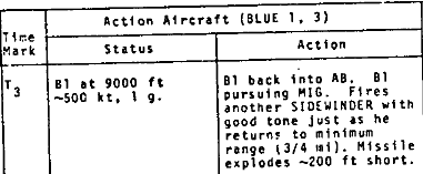
For all this engineering, the Sidewinder 1A's performance was unimpressive.
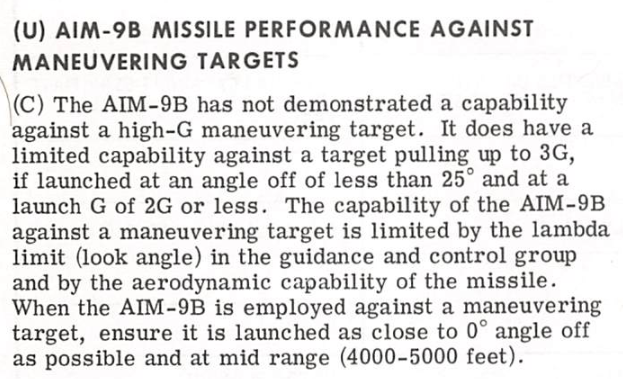
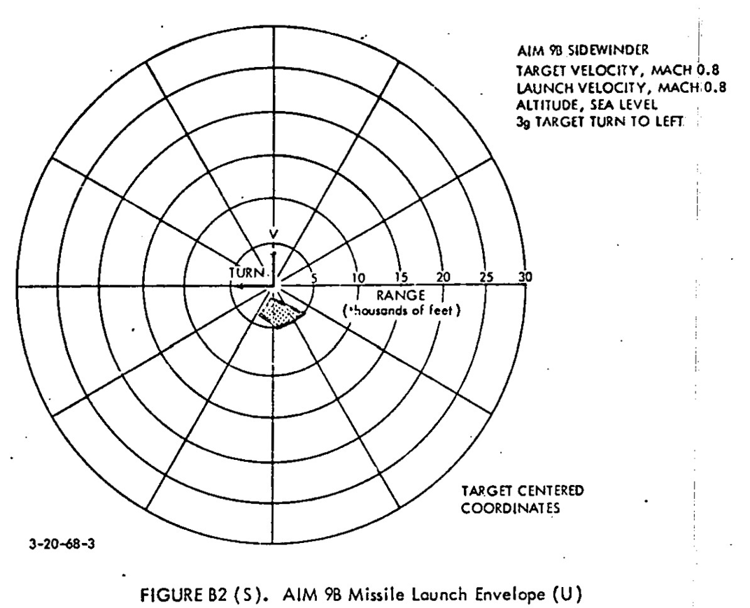

It also suffered from some guidance issues, such as overcorrection of spin-scanned inputs leading to the signature sidewinder "wobble" in flight. This tended to lower accuracy, especially against a maneuvering target, forcing reliance on the proximity fuze.
The program goals of Sidewinder were met, though. It was much lower cost than the Hughes Falcon, easier to produce and maintain, and easier to integrate onto existing fighters.
Nonetheless, engineers at NOTS China Lake were already developing a better Sidewinder.
Nonetheless, engineers at NOTS China Lake were already developing a better Sidewinder.
• • •
Missing some Tweet in this thread? You can try to
force a refresh