let's find out how this LED bulb works. 
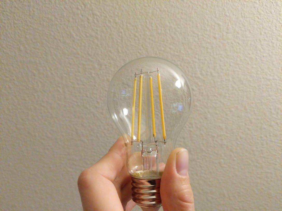
there's a tiny round circuit board underneath the sealed part of it! but i want to get to the LEDs.
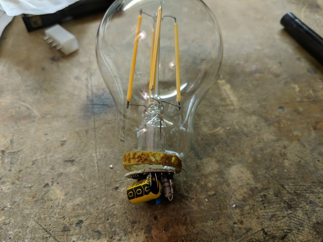
OK, wow, that bulb made a loud pop when i cracked it open with the help of concrete and a screwdriver.
i've clipped out an individual umm light stick? light saber?
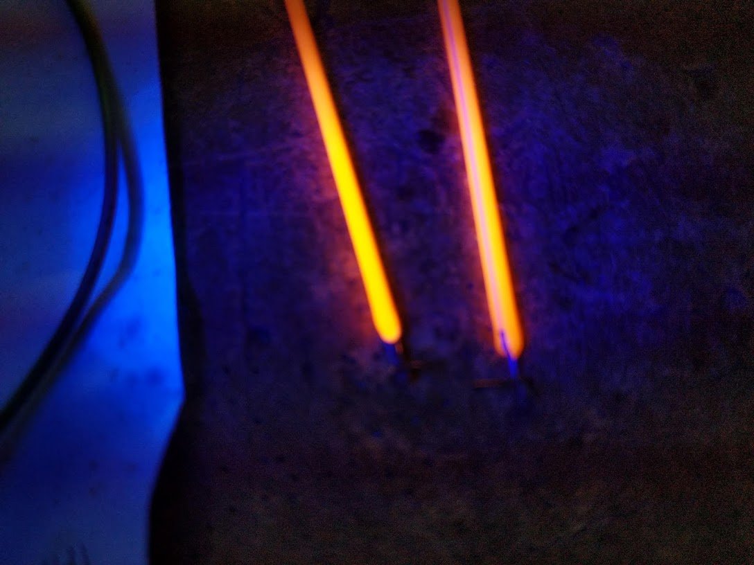
this is at 50 microamps of current and around 60V (with a 1K current limiting resistor, of course). you can see 25 individual points of light.
this is at 50 microamps of current and around 60V (with a 1K current limiting resistor, of course). you can see 25 individual points of light.
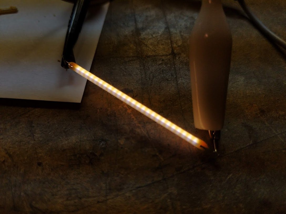
here it is at 1mA. this is only about 70mW, so this LED lamp is quite efficient.
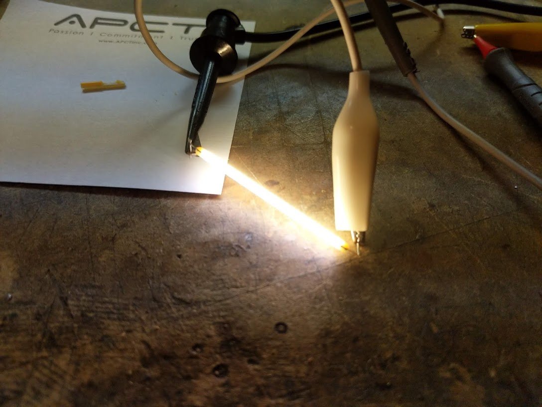
but i want to take it apart further. you can't get an LED die this long!
all right here we go. there's a train of tiny blue LEDs glued to a ceramic strip each tied to the next with a thin aluminum bond wire. the outer covering seems to be silicone mixed in with a phosphor.
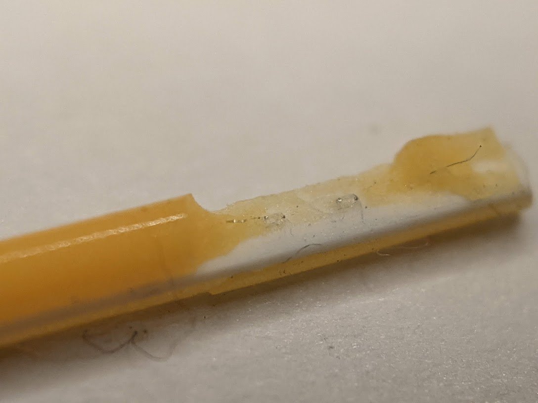
the phosphor in the silicone fluoresces when exposed to UV light. reminds me a bit of a CRT phosphor but i'm sure the chemistry is different.
now let's look at the circuit board. it's got a bridge rectifier, some off-brand capacitors, a fusible resistor, and two chips. SM2082. hmm.
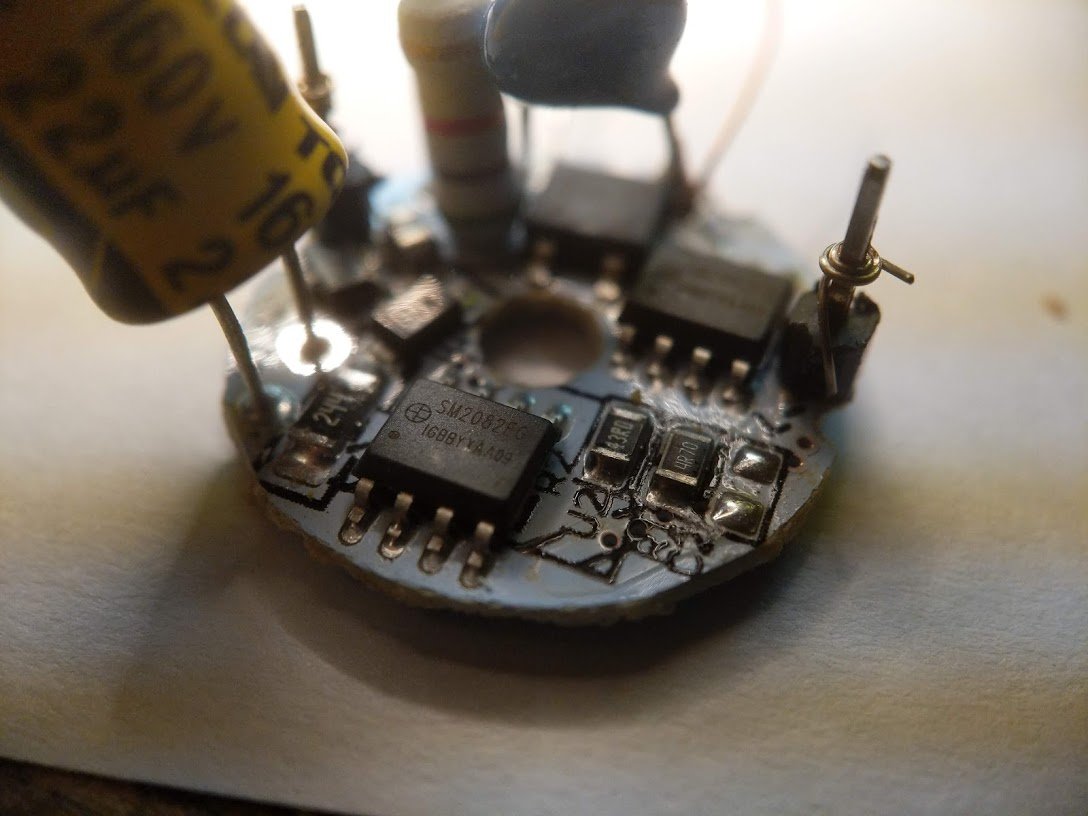
ahh it's a constant current LED driver chip. LCSC has them in stock, naturally. they appear to be less than 5 cents each in quantity! lcsc.com/product-detail…
that's incredible! the SOIC package alone costs something like 2 cents. maybe they've figured out how to get them even cheaper.
here's the typical circuit from the datasheet. basically the external resistor sets the current. it's linear, so the chip just dissipates the power drop across it. a switching converter would be more efficient, but the current is so low it probably doesn't matter.
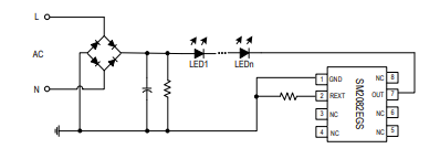
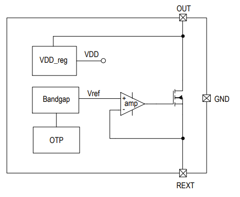
pretty classic current sink circuit. i guess the OTP is for trimming the bandgap. there's probably some test mode that lets them clock in digital data to the OTP cells.
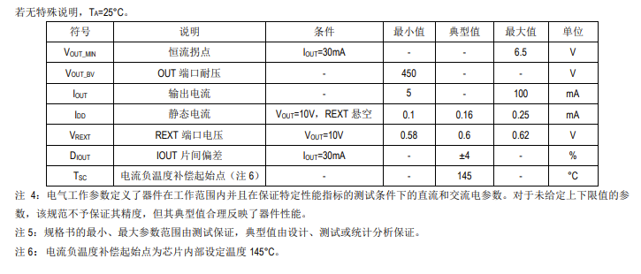
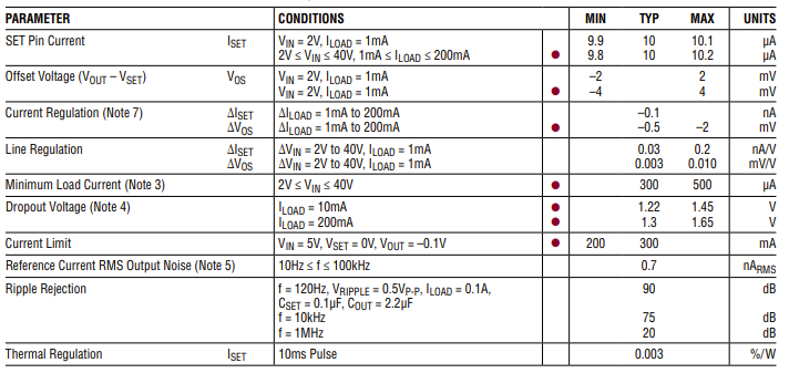
wow, they actually have some guaranteed test limits! about all i recognize is 小 (small) and 大 (big) but i haven't put any effort into learning Chinese. for the rest, there's Google Translate.
naturally, there's an equivalent part from a US chip company, the LT3092. it's not really a fair comparison.
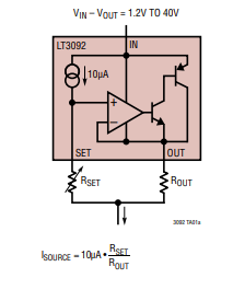
for one thing, the chip sells for $11 each. that's about 200 times the price of the Chinese part!
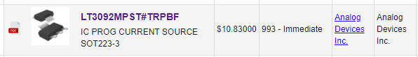
and yeah the specs are way more thorough and quite a bit tighter. you'd use the US part for some sort of precision instrumentation, never for a high volume consumer product.
anyway someone asked about dimming LED lamps. it can be tricky if the lamp uses a switching supply. but with a linear it's not bad. most dimmers use triacs and chop the AC waveform like this.
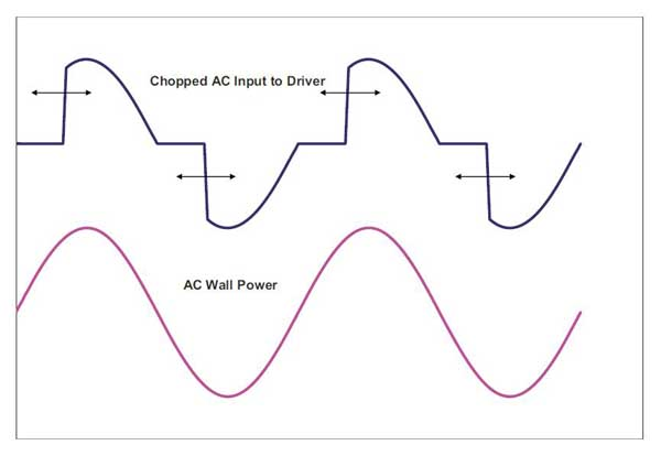
with this bulb, the chopped waveform gets turned into pulsating DC by the bridge rectifier and then RC filtered into a DC voltage that is kind of related to the dimmer setting
i haven't backed out the circuit but my guess is they're feeding a little sample of the DC voltage into the current set pin of the linear regulator.
(there'll be a series resistor to turn the voltage sample into a current)
ok i started digging into reverse engineering the circuit they use and there are a number of things i did not expect to see. more details later.
here's the circuit. while you stare at that I'm going to put together a bench setup and take some measurements

isolation transformer, variac, and dimmer. let's go check out some waveforms!

wow the dimmer really distorts the waveform. instead of a nice sine, it starts each cycle late. so the voltage spikes up quickly and then decays.

all right let's look at some lamp circuit waveforms. top waveform shows the pulsating DC that has been smoothed out somewhat by C1. mid waveform shows how U1 regulates the LED current. bottom waveform is the current sense voltage. peak corresponds with ~140mA through the LEDs.


now i'm looking at the voltage across a mystery part, Q1. i've drawn it as a zener diode with a cap hanging off the side. it seems to drop about 18V and tries to keep the voltage at the LED anode constant.


it's a SOT23 with the marking "A1401" and "1001". pin 1 goes to the cap, pin 2 to the LED anode and the cap, and pin 3 goes to input power. I'm guessing it's a shunt regulator of some kind, not a simple zener or transistor.

ok think i have this more or less figured out. the circled area is the main "make light" circuit. U1 is a constant current sink set to about 128mA. C1 and the resistor smooth out the pulsating DC from the rectifier so the lamp won't flicker.
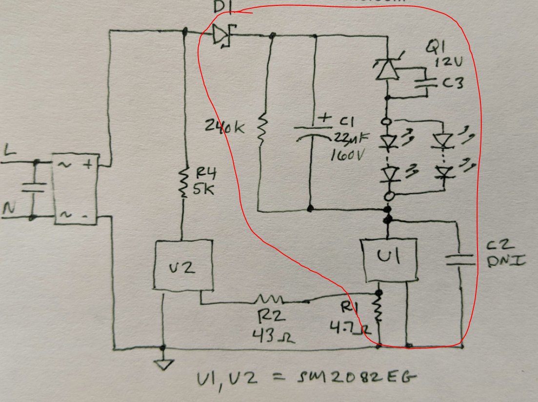
but what does U2 do? if i remove it, the lamp will not work at all on a dimmer! U2 is another constant current load, this time set to about 12mA. it is required for the dimmer to work--the dimmer needs to see a load even at low voltages.

see, due to the forward drop of the LEDs, they won't turn on until the input voltage gets fairly high (maybe 150VDC or more). this confuses the dimmer.
ok, so why does the current flowing through U2 go through R1 also instead of straight to ground? that is because the lamp needs to regulate the *sum total* current of both the dummy load and the LEDs. otherwise the LEDs will "bounce" in brightness as you adjust the dimmer setting

side note about U1 and U2: they regulate current using an internal op amp that servos the voltage on the drain of the FET so that the voltage across the external shunt resistor is 0.6V. it's very simple.

next topic: this lamp SUCKS and could burn your house down!!! let's dig into why that is.
i took apart 2 lamps from this batch. notice something different between the boards? what's that thing underneath the heat shrink?

it is a fusible resistor! this is a 10 ohm device that is supposed to act like a fuse and blow open if the lamp driver fails. AND THE OTHER BOARD DOESN'T HAVE ONE!!!

what this means is that i can't trust this entire batch of lamps, or even this manufacturer. some lamps have no fuse! but there's no way to tell which ones.
and it gets worse ☹️
see this big filter capacitor? i measured the voltage across it, and when the AC line voltage is 120V, the DC voltage is 157V! it is *right up against the rating of the cap* with utterly no margin! this is really, really bad.


with the voltage right at the rating and operating in a hot location, this capacitor isn't going to last long. and when it blows up, there's no fuse to limit the current.
likely this would trigger a cascading set of failures which could lead to a fire. and oops, there goes the house.
notice anything missing from this label?

there's no UL mark! just ETL. and that number is not in their database!
also 18 year life? lol. this label lies.
also 18 year life? lol. this label lies.

don't buy this brand. it's just not worth it. i suspect the same lamp is sold under a bunch of different brand names at Amazon and eBay and Aliexpress.

oh yeah and to the 1,231,437 people who keep asking me "have you see this bigclive video?" () the answer is yes, i subscribe to his channel
it's funny how i can always tell when The Algorithm is promoting a particular video. i should do a thread about that.
• • •
Missing some Tweet in this thread? You can try to
force a refresh