1/n This past weekend I gave two lectures @HarvardCMSA on “intrinsic triangulations” and how they can open new doors in geometric computing.
Videos here:
And details about the (terrific!) event here: cmsa.fas.harvard.edu/frg-2021/
Videos here:
And details about the (terrific!) event here: cmsa.fas.harvard.edu/frg-2021/

2/n The story begins with the transition in the 19th century from thinking about geometry in terms of points in space (extrinsic) to thinking about the broader ways we can describe shapes without knowing how they’re embedded (intrinsic).

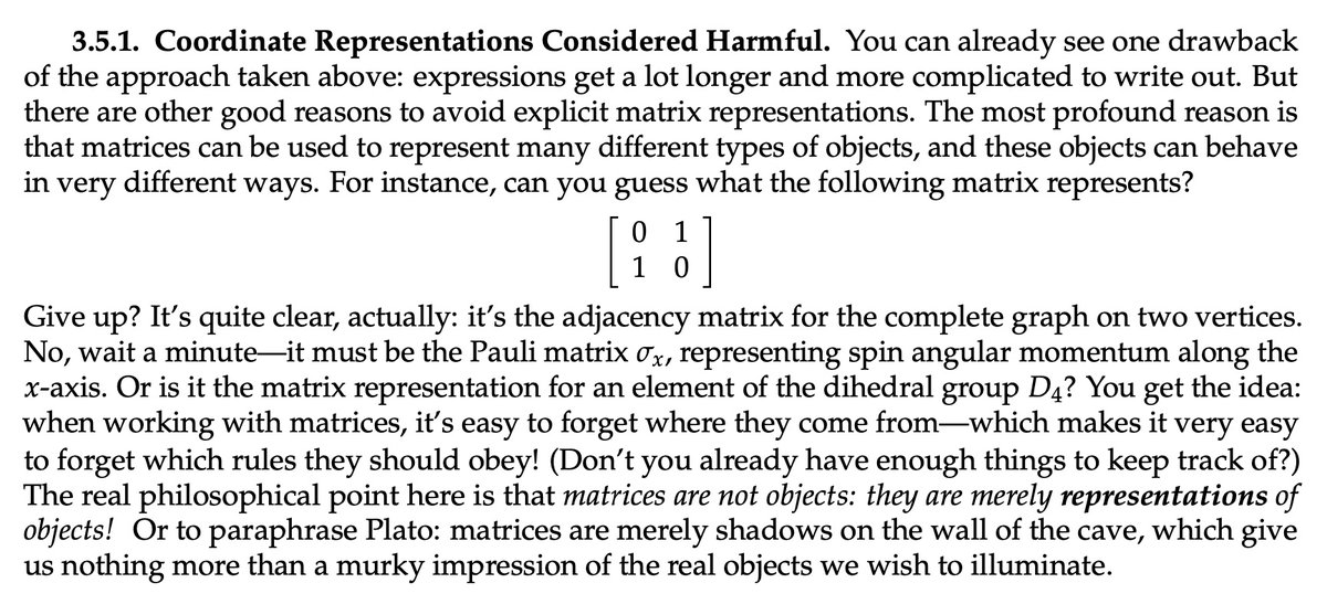
3/n Even though the intrinsic picture is now commonplace in mathematics, it’s still not how most people think about mesh processing. Almost universally we still describe the geometry of a mesh using Cartesian coordinates in a global coordinate system—just as we did in the 19th c.

4/n An alternative is to throw out the vertex coordinates and describe a mesh by its connectivity, plus edge lengths that describe just the local shape of each triangle. This is what I’ll call an “intrinsic triangulation.”
5/n Things get particularly interesting when this intrinsic triangulation actually comes from tracing out straight paths along a standard (“extrinsic”) triangulation. Even though these triangles look “bent,” they become ordinary triangles when unfolded into the plane.

6/n Ok, but why is it useful to “draw” one triangulation over another? It turns out there are a lot of good reasons, which can be motivated from three different angles.

7/n One angle is classic computational geometry. To improve a mesh in the plane while preserving its vertices, you can flip edges. But if you’re asked to also preserve the edges... that’s annoying! At best you can refine the mesh and hope the elements get better as you refine.

8/n Well, this “annoying” situation is *always* what you face in 3D: if you want to preserve the original geometry, you have to preserve vertices and edges—and hence refine like crazy. ...Unless you allow yourself to draw an intrinsic triangulation on top of the given one!

9/n In essence you’re now doing computational geometry on a polyhedral background domain, rather than a planar one. And so many classic planar algorithms can be “ported” to curved surfaces in a natural way.

10/n Another, related perspective is scientific computing, where your mesh must simultaneously play two roles: it defines the shape of the object being simulated, *and* provides the basis functions used to approximate the solution.

11/n When you start to build meshes in this setting it feels like a “no free lunch” situation. You want a good approximation of the geometry, with high-quality finite elements, while keeping the mesh small.
Traditionally, you get to pick just two.
Traditionally, you get to pick just two.

12/n But if you relax your definition of a mesh, and allow your “simulation mesh” to be traced out over your “geometry mesh,” you can get the best of all worlds: a reasonably small mesh with great element quality and which perfectly captures the original geometry.

13/n What’s happened here is that you’ve de-coupled the mesh defining the bases from the one used to describe the geometry. And of course, even though the geometry is piecewise linear doesn’t mean your basis functions have to be.

14/n Finally, the intrinsic picture is natural for geometry processing, where many algorithms are expressed in terms of intrinsic objects (Laplacian, geodesic distance, Gaussian curvature...). Why then bother processing the mesh extrinsically?

15/n Another big motivation for intrinsic triangulations is robustness. Anyone who has worked with real data knows meshes can be really, really bad.

16/n And unfortunately this problem is not going to resolve itself. What we consider to be a “bad mesh” is just getting *worse* in time, as technologies like 3d scanning and printing become commonplace. How can we “hide” the challenges of meshes from most users?

17/n The elegant solution from numerical linear algebra is to encapsulate a series of complex transformations in a simple black box interface (like “backslash” in MATLAB). Turn the system into something nicer, that can be solved by less-robust algorithms.

18/n Likewise, rather than making geometric algorithms more robust one algorithm at a time, intrinsic triangulations help provide “robustness as a subroutine.” Retriangulate under the hood, run a standard algorithm, return the result—all without changing the geometry.

19/n Anyway, that’s just a little motivation & sneak preview. The lectures cover some of the latest and greatest data structures for doing this kind of thing, a bunch of fun algorithms, and a list of interesting open questions. Check it out!
• • •
Missing some Tweet in this thread? You can try to
force a refresh