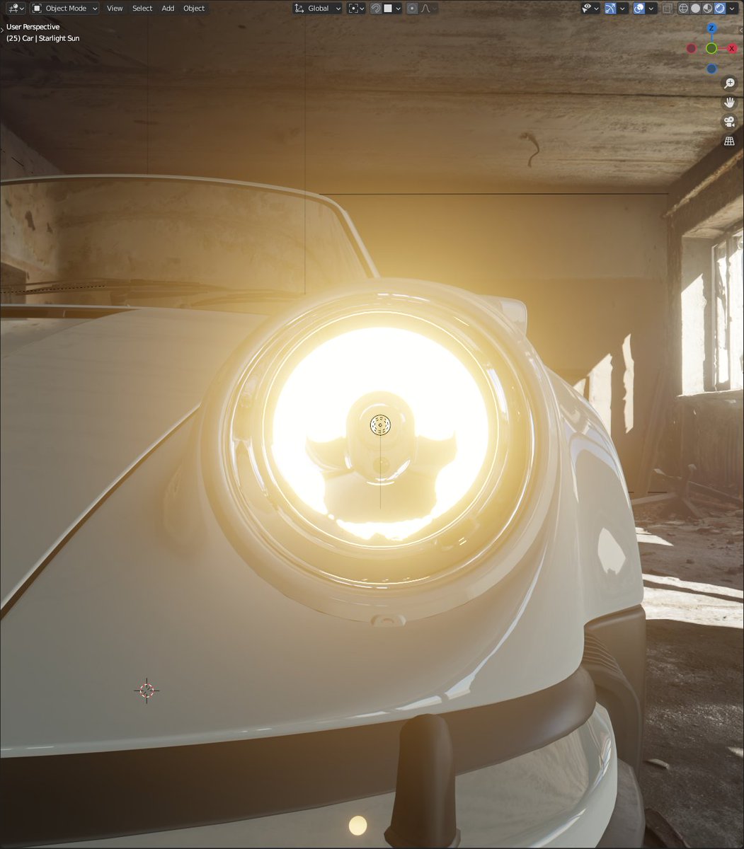
Last day before I take my time off work and I spent it tinkering with car headlights again!
This time I am exploring polarised light and thin-film interference on a transparent body in Blender.
Thank you @KarolMiklas for car model! Beautiful work as always 🙏
Follow the 🧵👇
This time I am exploring polarised light and thin-film interference on a transparent body in Blender.
Thank you @KarolMiklas for car model! Beautiful work as always 🙏
Follow the 🧵👇


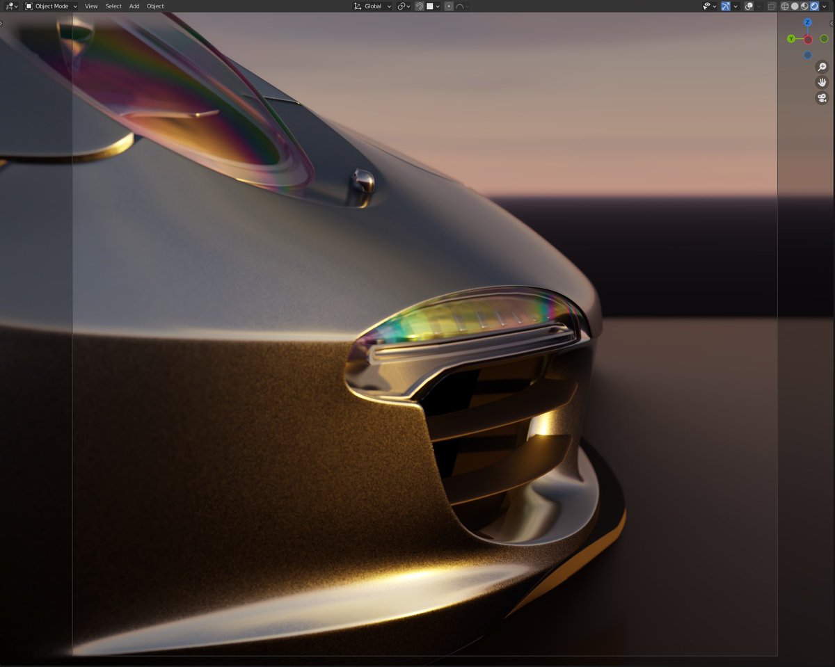

Polarised light and Thin-film interference are not the same in terms of physics. One is caused by injection moulding of the plastic, other - by a very thin layer of material on the surface of another material.
Both offer similar looks, so I use the same technique to model it.
Both offer similar looks, so I use the same technique to model it.

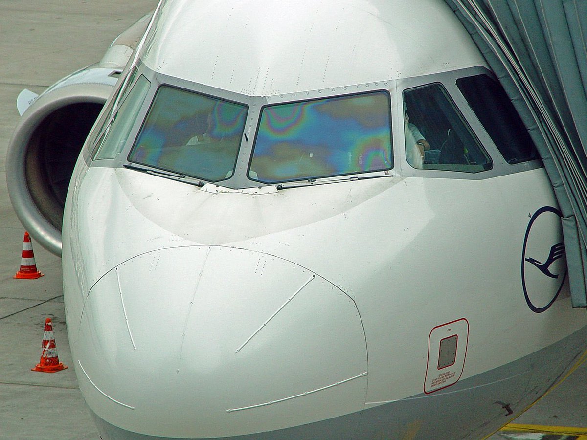
Here are two real-world examples. ‘Colorisation’ on the headlights are caused by polarisation while on windshield - by a defrosting coating. Most people, including me, mixes these, so for an artist like me, a single approach to tackle both problems, is working just fine! 👌

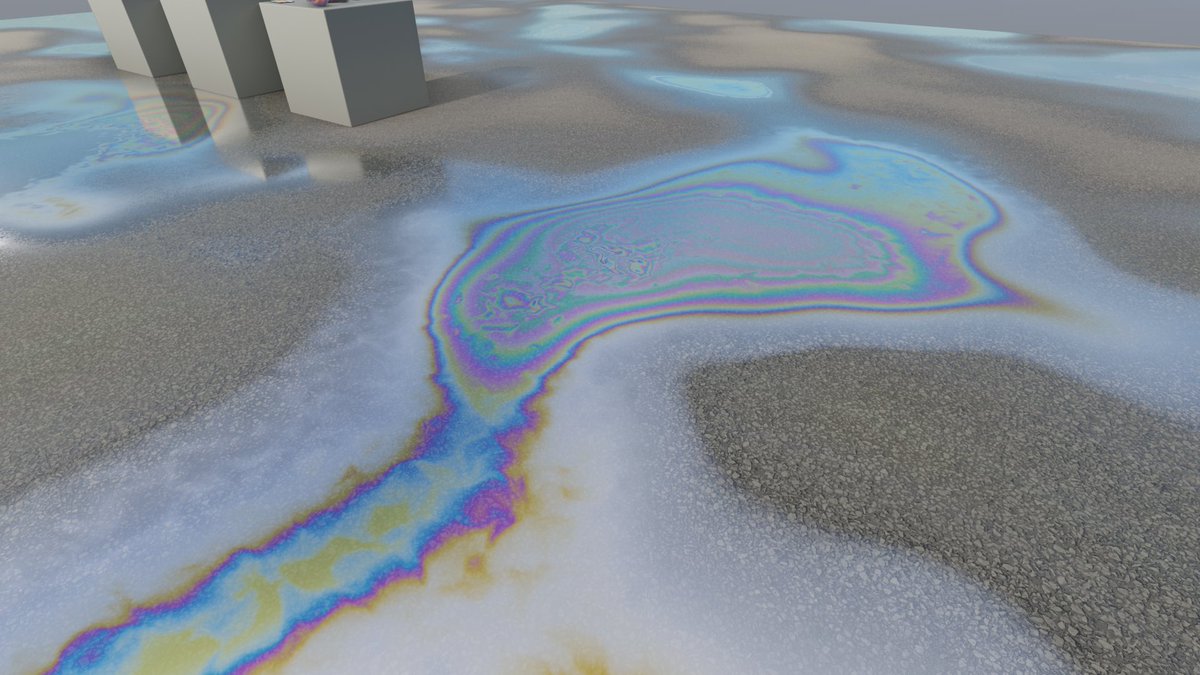
Mostly thin-film interference is a beautiful accident caused by an oily cleaning liquid or gasoline (🌈 in puddles), but if used on purpose, you can have very effective light blocking sunglasses or obnoxious car headlights. Also those anti-glare coatings on lenses work this way.


Before I move on to ‘praxis’ part. I just want to establish some theory before, so you learn something too. I will keep it simple.
Also, this is a work in progress. I don’t know everything, I’m learning on the go. So if you know things about the topic, please correct me.
Also, this is a work in progress. I don’t know everything, I’m learning on the go. So if you know things about the topic, please correct me.
I’ll start with light polarisation.
As I mentioned, it is an inevitable side-effect of moulding. It reveals the flow of liquid plastic and high tension points in the structure. It can easily be seen with a polarisation filter and any plastic object in your household.
#nftart
As I mentioned, it is an inevitable side-effect of moulding. It reveals the flow of liquid plastic and high tension points in the structure. It can easily be seen with a polarisation filter and any plastic object in your household.
#nftart

Polarisation difference from thin-film interference (TFI) is that the ‘colorisation’ is not in reflected light, but happens during transmittance. It makes the colouring look less vibrant than of TFI and can filter out the light completely.
Why we can see it with naked eye on some car headlights? 🤷
My guess is that car manufacturers use polarised coating to filter light from projectors, but as a result - reveal the imperfections in the glass body. Perhaps also glass is polarising itself at some angles. Thoughts?
My guess is that car manufacturers use polarised coating to filter light from projectors, but as a result - reveal the imperfections in the glass body. Perhaps also glass is polarising itself at some angles. Thoughts?

Thin-film interference is more straightforward. It is a very thin ‘film’ of transparent material with a different density (and IOR) than the material it in contact with. The layer is so thin that light waves start ‘glitching’ from the phase change from surface reflections.

Now we know a little more about the mechanics behind both effects, but I bet it does not help you replicate the effect now by yourself. And it is not really trivial too.
Luckily smart people have figured it out before me and I can just take their findings and adapt for my needs.
Luckily smart people have figured it out before me and I can just take their findings and adapt for my needs.
Et Voilà, here it is! After many tries with different shader based procedural approaches, I have found that LUT technique is the fastest and most accurate. I used the method from the awesome thread by @amandaghassaei
https://twitter.com/amandaghassaei/status/1348006462824484865
Happy holidays! ⛄️ I have a moment to continue the thread.
So how do you use that rainbow-y LUT texture in Blender?
That LUT is a plot of soap bubble TFI where horizontal (x) axis is film thickness in nanometres (1-2500 nm) and vertical (y) axis represent view (incident) angle.
So how do you use that rainbow-y LUT texture in Blender?
That LUT is a plot of soap bubble TFI where horizontal (x) axis is film thickness in nanometres (1-2500 nm) and vertical (y) axis represent view (incident) angle.
- download this LUT
- drop into shader Node editor and set to linear (?)
- add ‘combine XYZ’ node and connect it to the texture ‘Vector’ input.
- in ‘X’ slot goes the ‘thickness’ value from 0.0 to 1.0
- in ‘Y’ slot - Dot product of surface Normal and View Vectors.
- drop into shader Node editor and set to linear (?)
- add ‘combine XYZ’ node and connect it to the texture ‘Vector’ input.
- in ‘X’ slot goes the ‘thickness’ value from 0.0 to 1.0
- in ‘Y’ slot - Dot product of surface Normal and View Vectors.

I forgot to mention that the apparent thickness of ‘film’ changes based the view angle of the surface. That’s why we need also ‘incident’ angle input on top of the ‘thickness’.
That’s what makes the iconic color shift at grazing angles.
That’s what makes the iconic color shift at grazing angles.

- Add three shaders ‘Refraction BRDF’, ‘Glossy BRDF’ and a ‘MIX Shader’.
- Add a Fresnel node and connect to ‘Mix Shader’ factor.
- Connect Refraction to upper and Glossy to lower shader inputs in ‘Mix shader’ node.
- make sure ‘roughness’ for both shaders is 0 ir close to it.
- Add a Fresnel node and connect to ‘Mix Shader’ factor.
- Connect Refraction to upper and Glossy to lower shader inputs in ‘Mix shader’ node.
- make sure ‘roughness’ for both shaders is 0 ir close to it.
for thin-film interference - attach the LUT output to ‘Glossy BRDF’ Color input and for polarised light effect - to ‘Refracfion BRDF’ Color input.
For Eevee make sure SSR is enabled in render settings and Refraction is ticked in material settings and ssr depth is close to 0.
For Eevee make sure SSR is enabled in render settings and Refraction is ticked in material settings and ssr depth is close to 0.
This will stay in written form till I get to PC, then I’ll snap a shot of node setup.
Meanwhile I have these.
left - film thickness low
mid - film thickness ~400nm
right - film thickness modulated with regular Blender 3D noise
Meanwhile I have these.
left - film thickness low
mid - film thickness ~400nm
right - film thickness modulated with regular Blender 3D noise


oil in a puddle test using blender noise for thickness modulation.
And here is my Shader Node setup. Upper Window - Material, lower - Thin-Film Interference node group.
This is by no means a definitive approach. I can see room for improvement and I am not sure if mixing with pure fresnel is accurate. But this is the best result I have so far.
This is by no means a definitive approach. I can see room for improvement and I am not sure if mixing with pure fresnel is accurate. But this is the best result I have so far.

• • •
Missing some Tweet in this thread? You can try to
force a refresh