Let’s take a look at JWST mirrors.
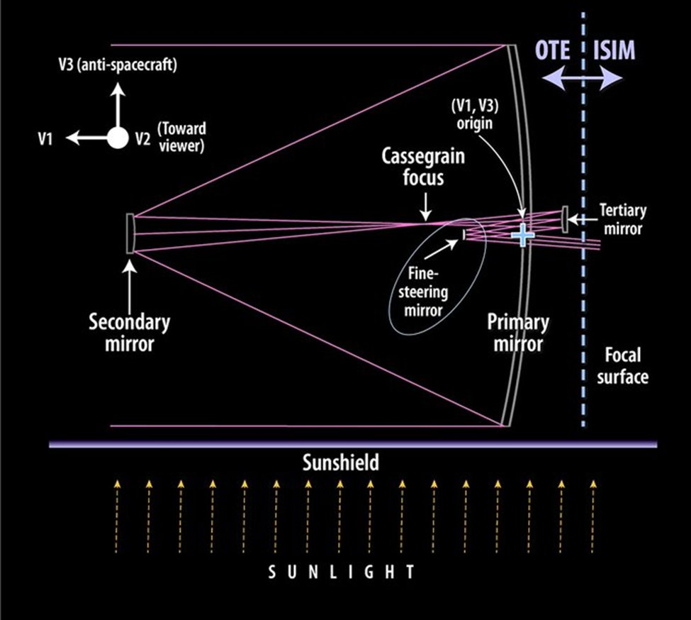
Besides the familiar large primary mirror, JWST contains 3 other mirrors – a secondary mirror mounted at the end of the tripod struct, a tertiary mirror and a fine steering mirror. The figure below shows the path of IR light across the mirrors.
Besides the familiar large primary mirror, JWST contains 3 other mirrors – a secondary mirror mounted at the end of the tripod struct, a tertiary mirror and a fine steering mirror. The figure below shows the path of IR light across the mirrors.

We all know that the JWST primary mirror is composed of 18 hexagonal mirror segments.
Each mirror segment is 1.3 meters from side-to-side, 2 inches thick and weighs 40 kg.
Each mirror segment is 1.3 meters from side-to-side, 2 inches thick and weighs 40 kg.

The mirror is made of Beryllium, atomic number = 4, a stiff and light-weight metal, 4.2 times lighter than steel, a good conductor of electricity and heat and excellent at holding its shape across a wide range of temperatures. 

The flat surface of each mirror has been precisely ground, polished and coated with a thin layer of gold; gold improves the mirror's infrared light reflectivity. A thin layer of amorphous SiO2 (glass) is deposited on top of the gold to protect it from scratches during handling. 

The following video shows the mirror's odyssey across the US. Fabrication steps include Beryllium ore mining and purification, pressing of Be and cutting of mirror blanks, shaping and polishing of mirrors, gold plating and cryogenic cooling and testing.
Each mirror can be independently shifted, tilted and bent using a set of actuators to achieve precise focus across all 18 segments.
The back of the Be mirror is milled out to reduce weight, leaving a honeycomb structure of ribs that provides stiffness and support to the mirror.
The back of the Be mirror is milled out to reduce weight, leaving a honeycomb structure of ribs that provides stiffness and support to the mirror.
A number of structures, many made with Beryllium, are mounted behind each mirror, including 7 actuators. Six (degrees of freedom (DOF)) actuators enable each mirror to be very precisely shifted and tilted to optimal position. 

The 7th radius-of-curvature (RoC) actuator and set of 6 struts enable the mirror surface to be bent and curved. The mirrors will be precisely aligned and curved after they reach their operational temperature in L2 orbit. They will fine-tuned every 2 weeks thereafter.
The secondary mirror is a circular convex shaped mirror, 0.74 meters in diameter, made of gold-plated Beryllium. The curvature of the mirror was created during fabrication and polishing. It is mounted at the end of the tripod-like secondary mirror support structure (SMSS). 

Here is a look at the fully assembled JWST mirror.
For more details, see jwst.nasa.gov/content/observ…
For more details, see jwst.nasa.gov/content/observ…

Here is a comparison of optical telescope primary mirror sizes. JWST and Hubble are at the bottom left.
JWST’s 6.5m mirror is 6.25 times large than Hubble’s 2.4m mirror, in light collecting area.
Source: commons.wikimedia.org...
JWST’s 6.5m mirror is 6.25 times large than Hubble’s 2.4m mirror, in light collecting area.
Source: commons.wikimedia.org...

Please take a look at this thread for how #JWST is pointed at its target of interest.
https://twitter.com/akaschs/status/1476588950135390208
For an enlightening technical chat about the optical design of #JWST and how it achieves an effective focal length of 131 meters, check out -
https://twitter.com/fox_ori/status/1479095280909926404
The GSE Handling Ring in the above JWST mirror pic is part of a test fixture and not used in flight.
The pic also clearly shows the machined out back side of the mirror with the egg-crate-like mesh structure providing support to the mirror.
Source: spiedigitallibrary.org/journals/optic…
The pic also clearly shows the machined out back side of the mirror with the egg-crate-like mesh structure providing support to the mirror.
Source: spiedigitallibrary.org/journals/optic…
The JWST actuators use stepper motors plus gears, couplers and cams to produce linear motion with sub-10 nm accuracy.
See authors.library.caltech.edu/91580/1/106983… for more details.
See authors.library.caltech.edu/91580/1/106983… for more details.

FYI - The JWST secondary mirror also uses actuators for positioning and tilting. I don't think it uses an actuator for curvature control.
Some additional info from spacesymposium.org/wp-content/upl… - the JWST primary mirror segments are curved during fabrication, but not to a very low tolerance. The RoC actuators will be used for precise modification of the mirror surface curvature during the next few months.
Some additional references on JWST mirrors, etc. -
spiedigitallibrary.org/journals/optic…
jwst-docs.stsci.edu/jwst-observato…
jwst.nasa.gov/content/observ…
nasa.gov/content/goddar…
spiedigitallibrary.org/journals/optic…
jwst-docs.stsci.edu/jwst-observato…
jwst.nasa.gov/content/observ…
nasa.gov/content/goddar…
Here is some more data on #JWST mirrors and their placement on the spacecraft. E.g., the secondary mirror is 7.169 meters away from the primary mirror. The tertiary and fine steering mirrors are slightly offset from the boresight line. EFL is the effective focal length. 

Here are pics of the #JWST tertiary and fine steering mirrors. Note that the tertiary mirror has a rectangle-like shape 0.728 m x 0.517 m. The fine steering meter is 0.172 m in diameter and has a similar shape as the primary mirror. 

Let's take a look at the unfolding and latching of the #JWST mirror wings yesterday. Each wing has 2 hinges, similar to door hinges. One of the hinges was driven by a motor, which rotated the wing into its position aligned with the main mirror assembly. 

The inner edge of the wing has 4 sets of latches. Each latch set contains 2 guide latches and one middle latch with a nut. The edge of the main mirror assembly has corresponding guide latches and the middle latches each with a screw. The screw is driven by a stepper gear motor. 

The screws were engaged once the wing was almost fully opened. It took a few hours yesterday to methodically align and fasten the latches and to achieve precise alignment of the wing mirrors with the main assembly.
See esmats.eu/amspapers/past… for more details.
See esmats.eu/amspapers/past… for more details.
That's our look at the #JWST mirrors 😇 

• • •
Missing some Tweet in this thread? You can try to
force a refresh


