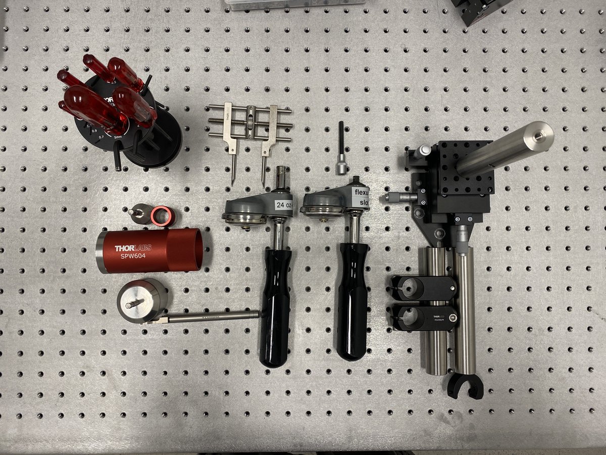
How do you put multiple optics in a row and align them so that their optical axes agree? This is a thread where I show you how I build a compact Alignment Laser Assembly– the companion to my "Alignment Crane" from a few months ago:

https://twitter.com/TanFad/status/1559187220291919874?s=20&t=LYYlG1bXE771GOxVSNx2Og
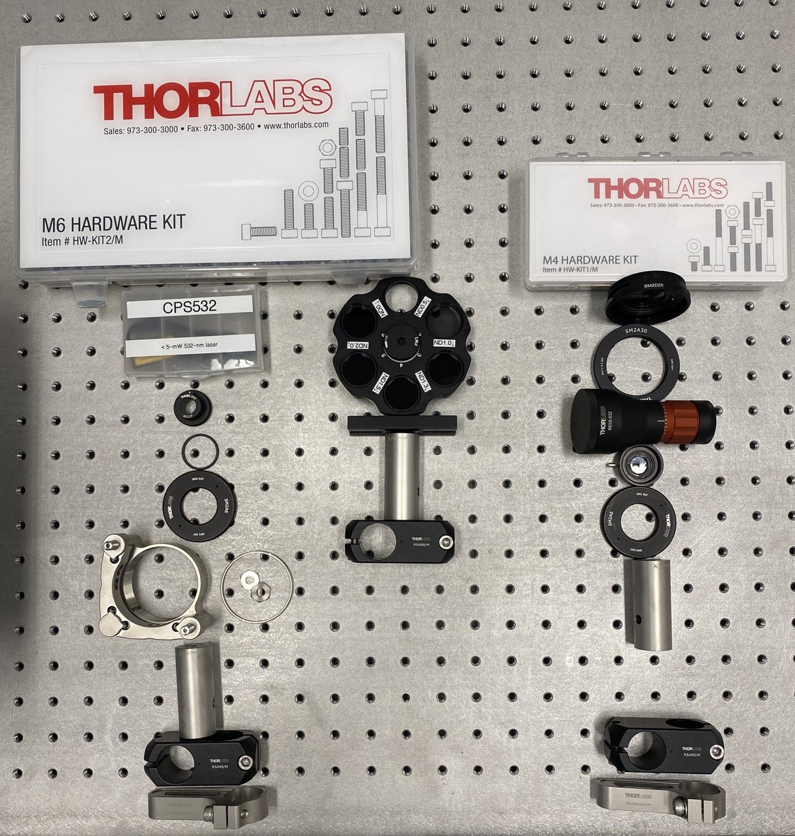
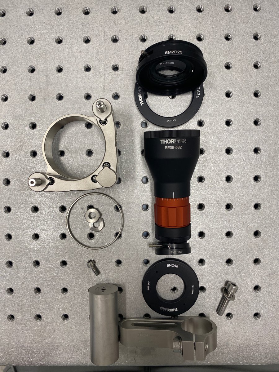
2/34 First, the parts. I’ll detail each part needed in each section, but here are the basic components needed for:
- the alignment laser assembly
- alignment readout tools
- mirrors for alignment laser steering
- tools for assembly
- the alignment laser assembly
- alignment readout tools
- mirrors for alignment laser steering
- tools for assembly
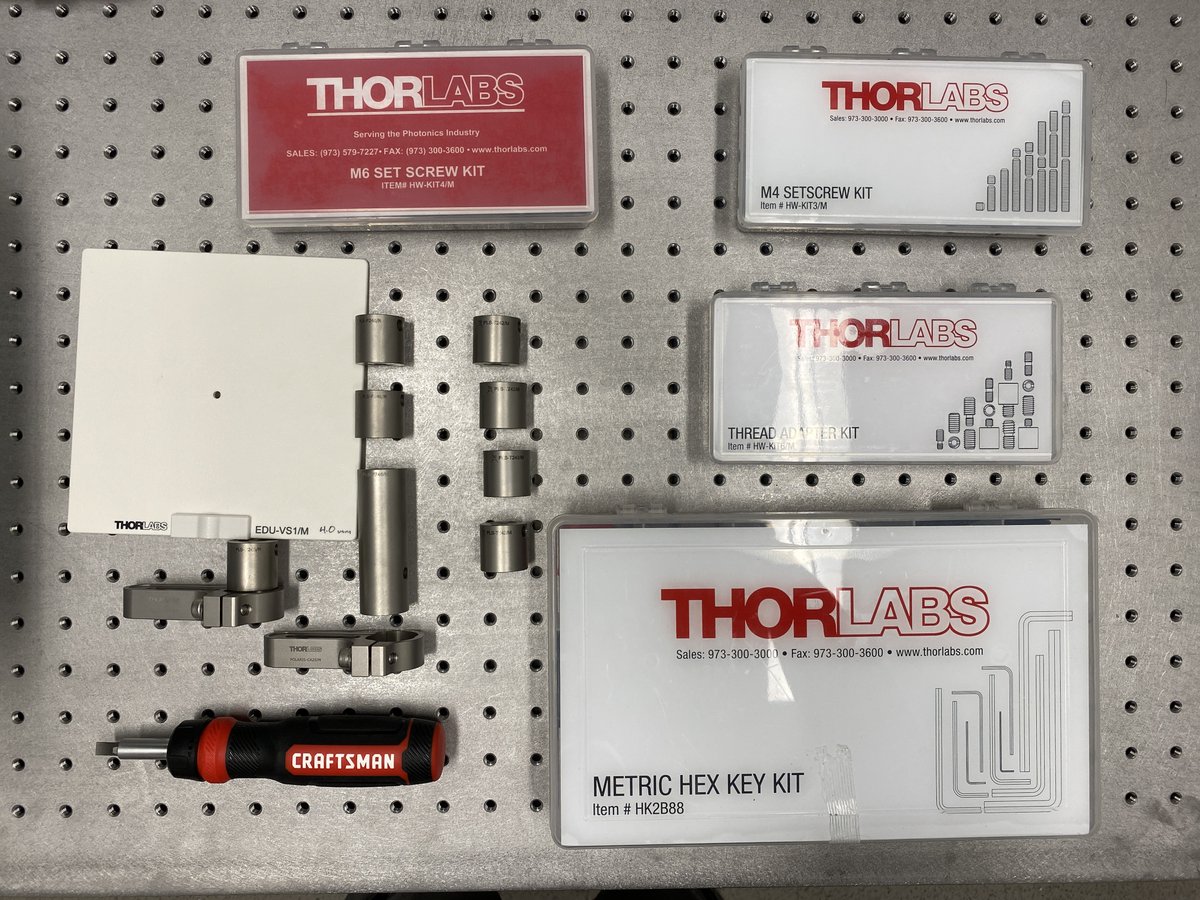

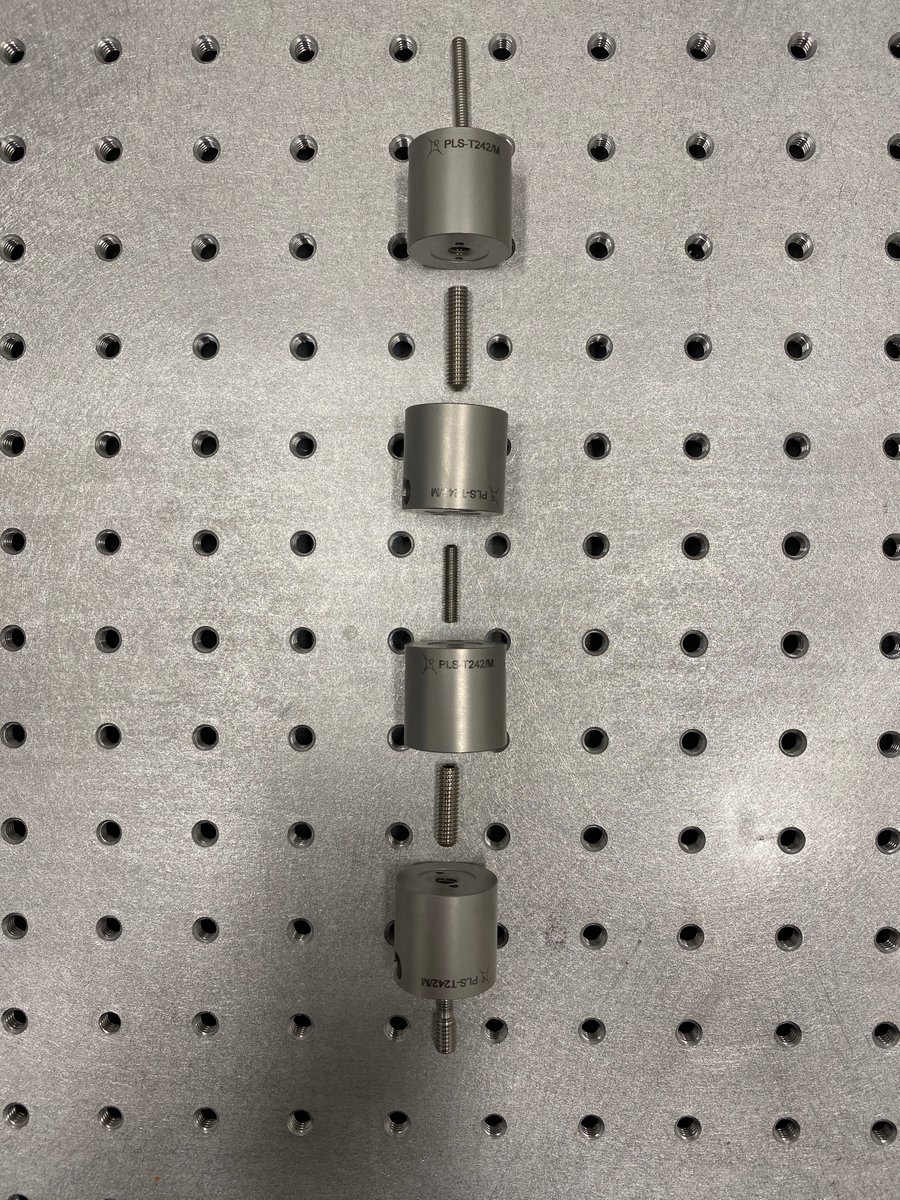
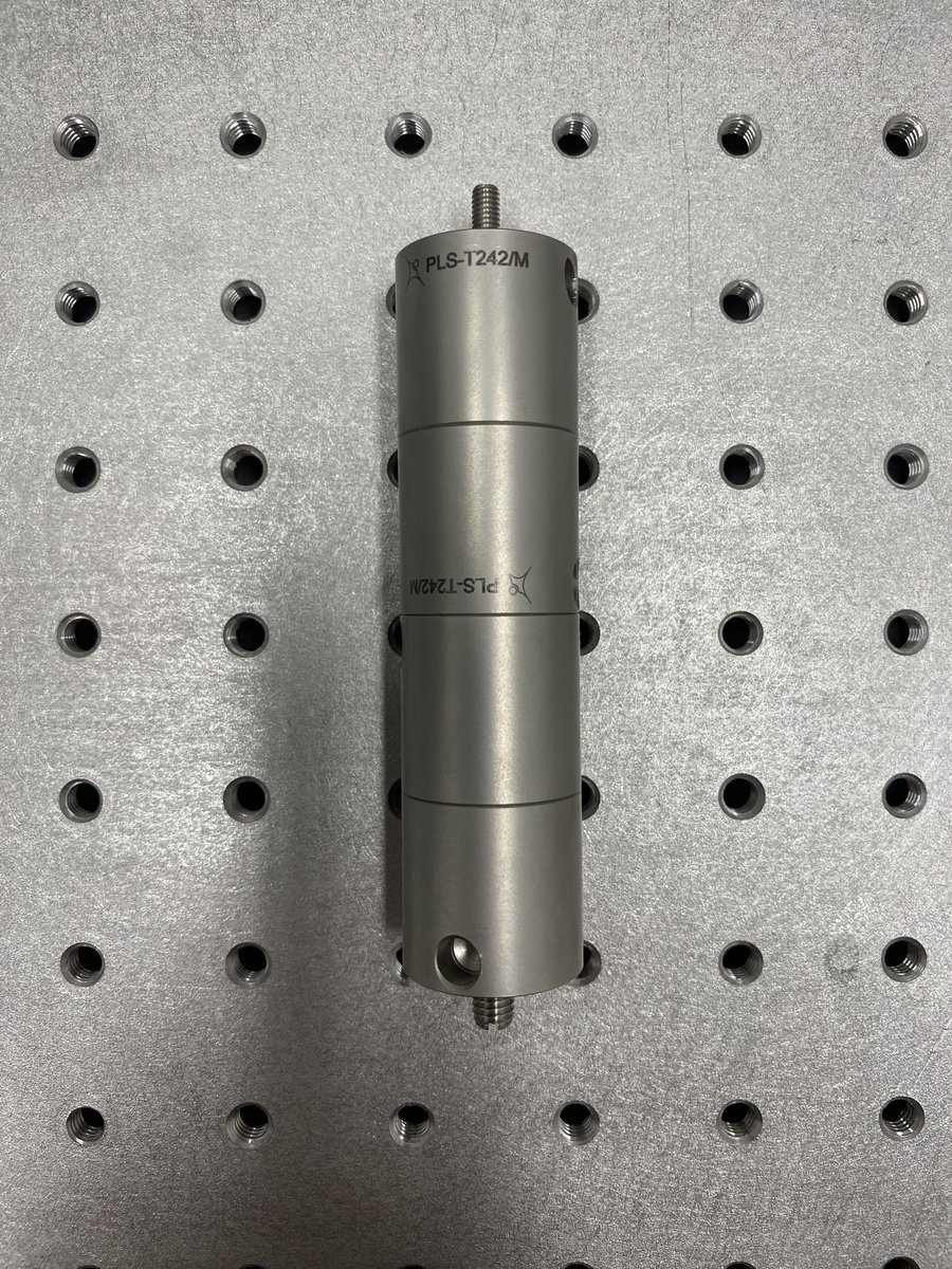
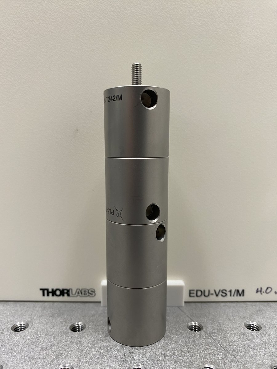
3/34 Horizontal alignment tool parts:
- 4 x PLS-T242/M
- 4 x M4 set screw
- 1 x M4-to-M6 external thread adapter
This alignment tool threads directly into an M6 breadboard. The beam will be ~100 mm off of the breadboard, so the final height of the posts should be <100 mm.
- 4 x PLS-T242/M
- 4 x M4 set screw
- 1 x M4-to-M6 external thread adapter
This alignment tool threads directly into an M6 breadboard. The beam will be ~100 mm off of the breadboard, so the final height of the posts should be <100 mm.
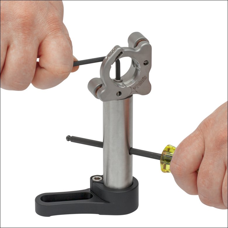
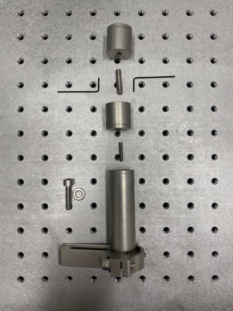
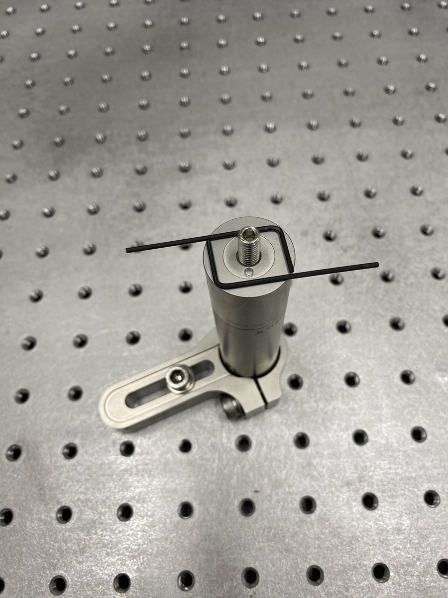
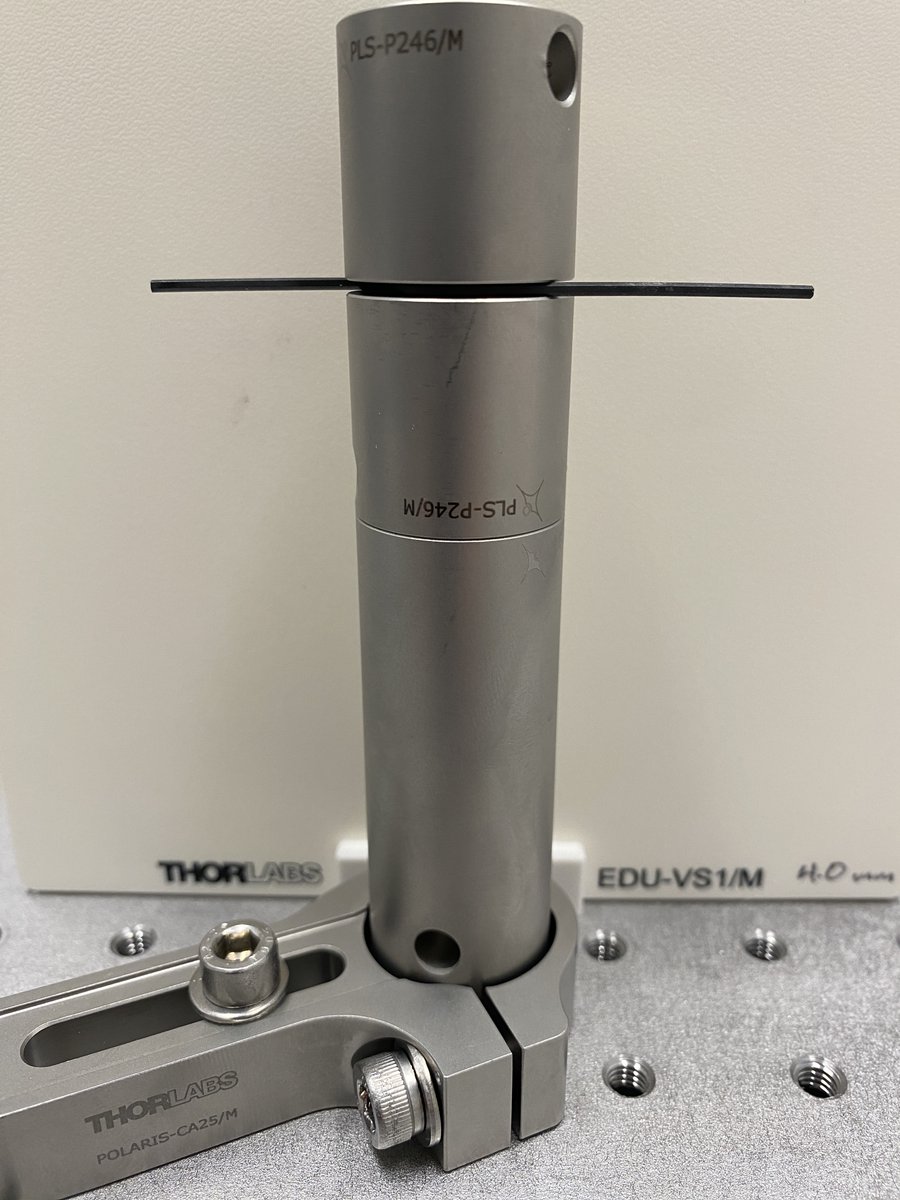
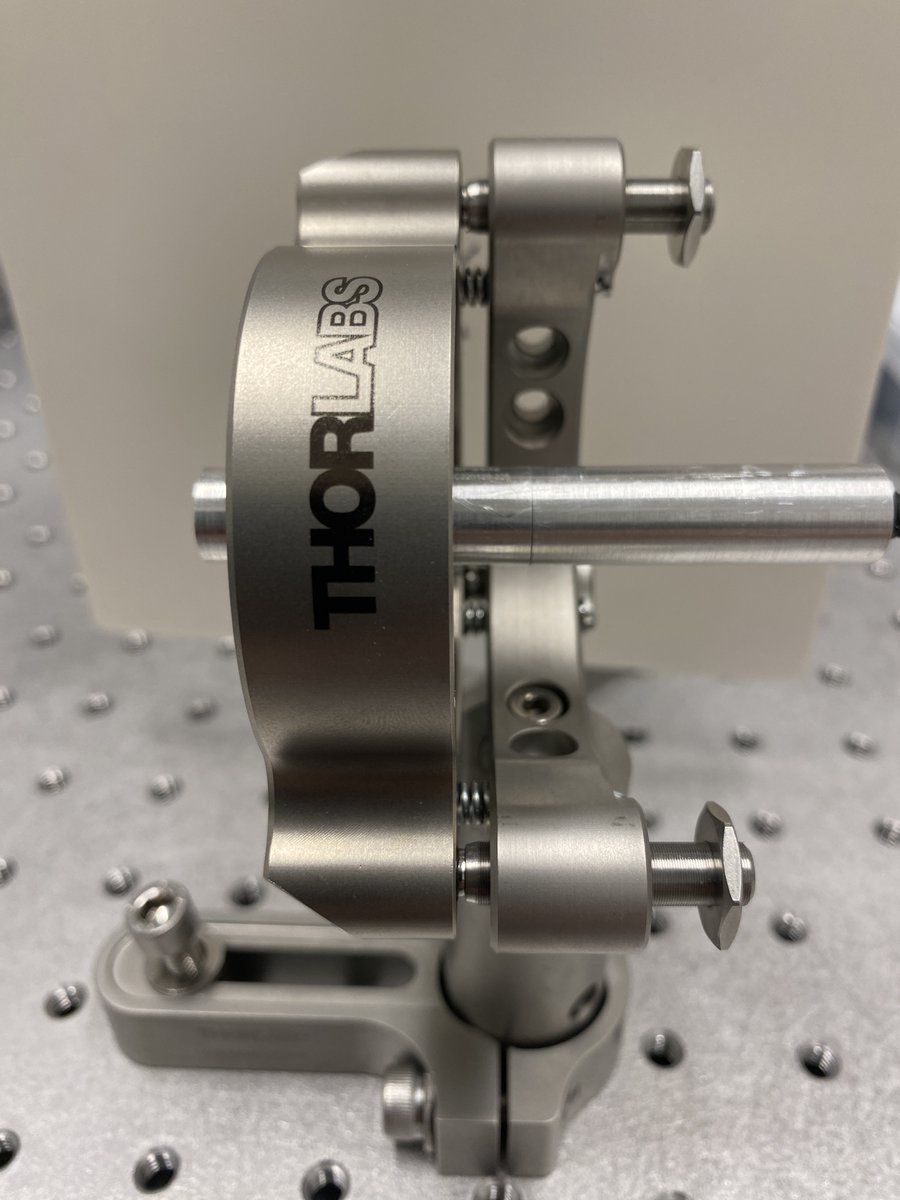
4/34 Vertical alignment tool parts:
1 x POLARIS-CA25/M
1 x PLS-P746/M
1 x M4 set screw
2 x PLS-P246/M
1 x M6 set screw
2 x 1.3 mm hex key
The vertical alignment tool uses a hex key as a reference height (~100 mm) for the initial laser and expander alignment.
1 x POLARIS-CA25/M
1 x PLS-P746/M
1 x M4 set screw
2 x PLS-P246/M
1 x M6 set screw
2 x 1.3 mm hex key
The vertical alignment tool uses a hex key as a reference height (~100 mm) for the initial laser and expander alignment.
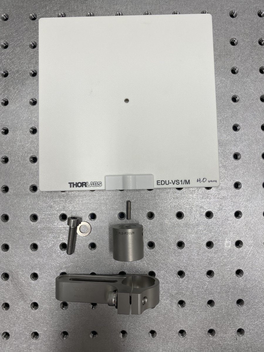
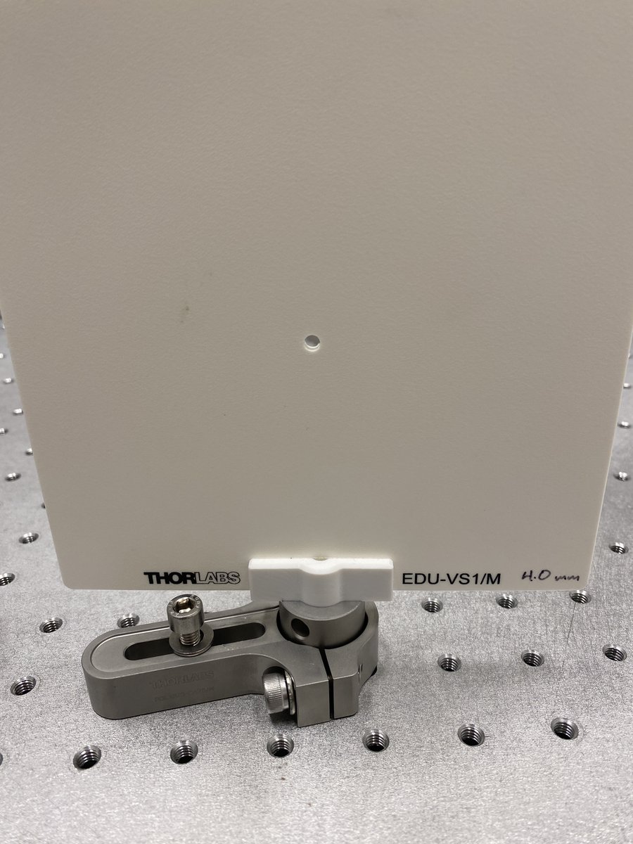
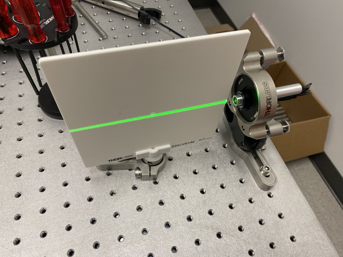
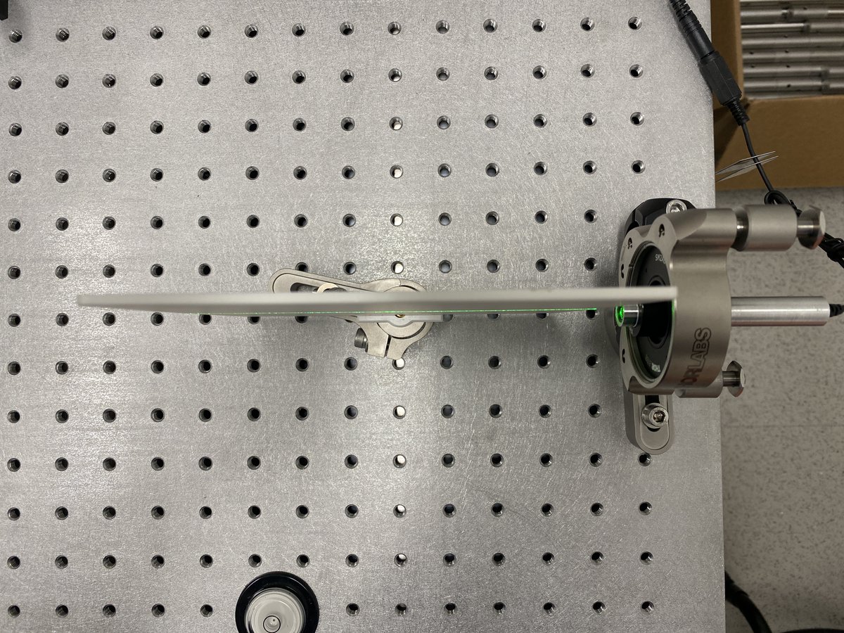
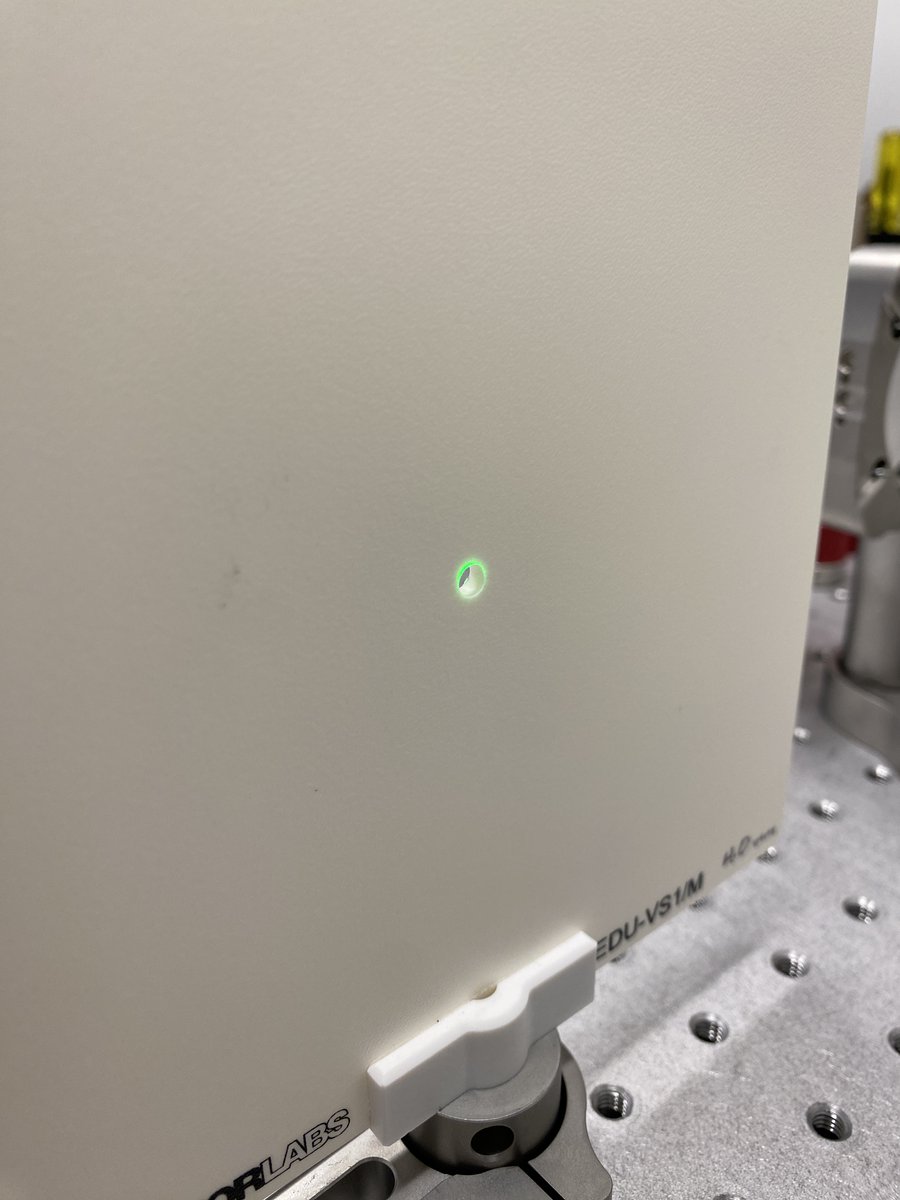
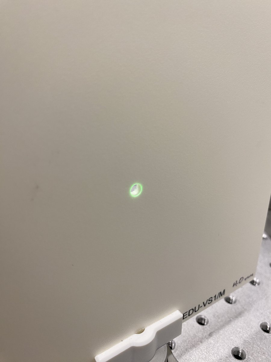
5/34 Viewing screen
1 x EDU-VS1/M
1 x PLS-P246/M
1 x POLARIS-CA25/M
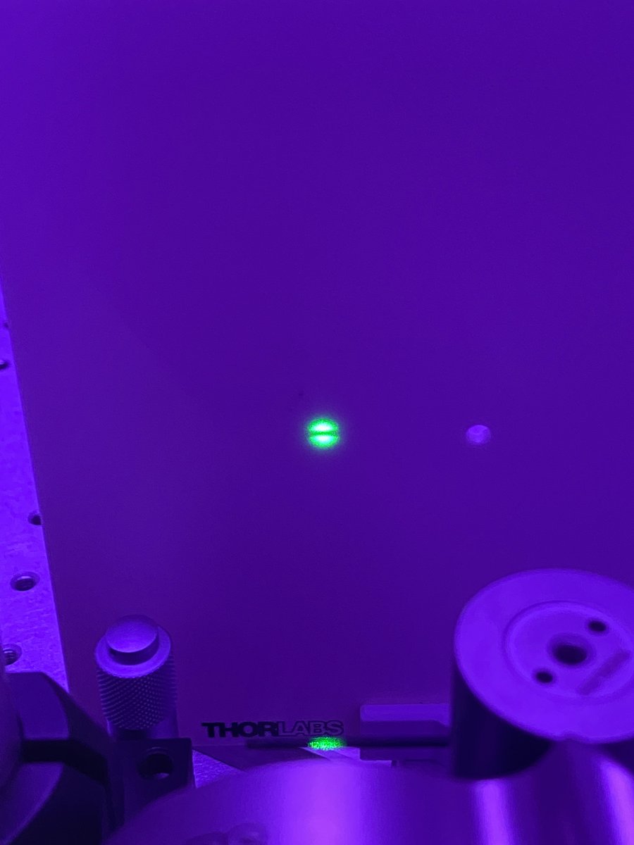
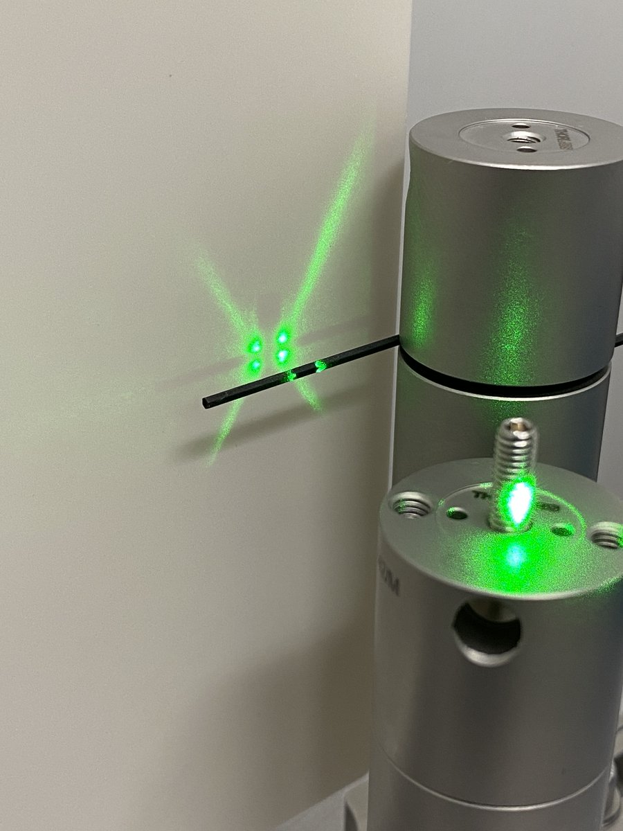
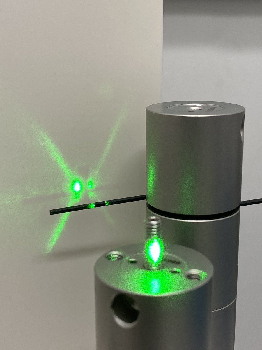
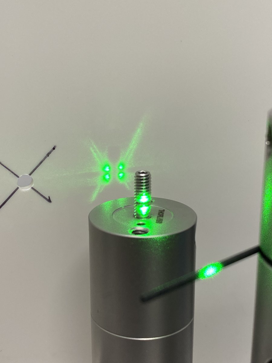
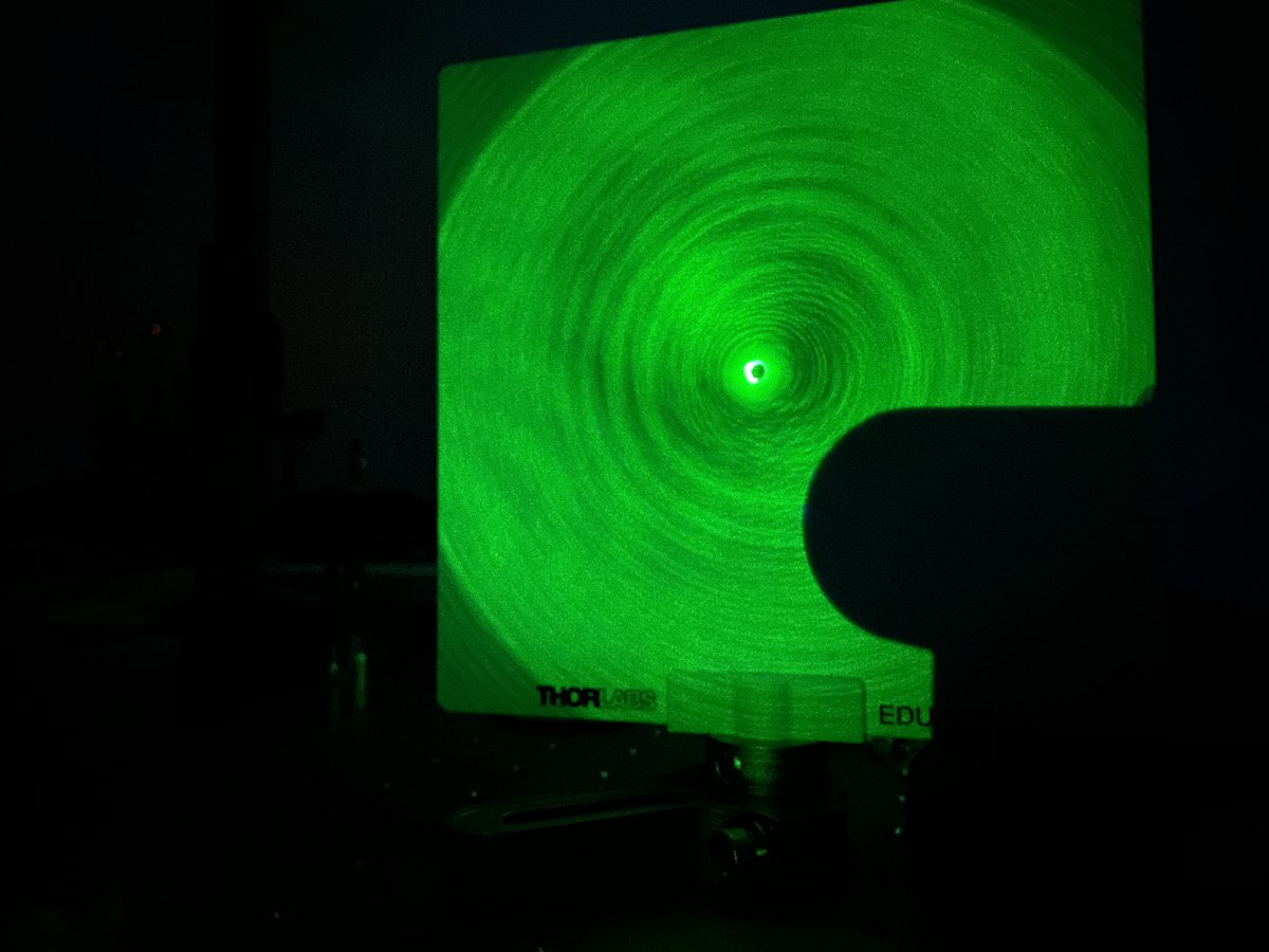
I highly recommend drilling a small (~4 mm) hole through the center of the viewing screen at the beam height, as it allows you to view back reflections from lenses. Back reflections are crucial for alignment!
1 x EDU-VS1/M
1 x PLS-P246/M
1 x POLARIS-CA25/M
I highly recommend drilling a small (~4 mm) hole through the center of the viewing screen at the beam height, as it allows you to view back reflections from lenses. Back reflections are crucial for alignment!
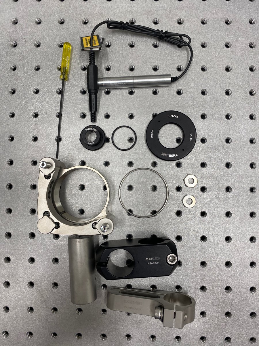
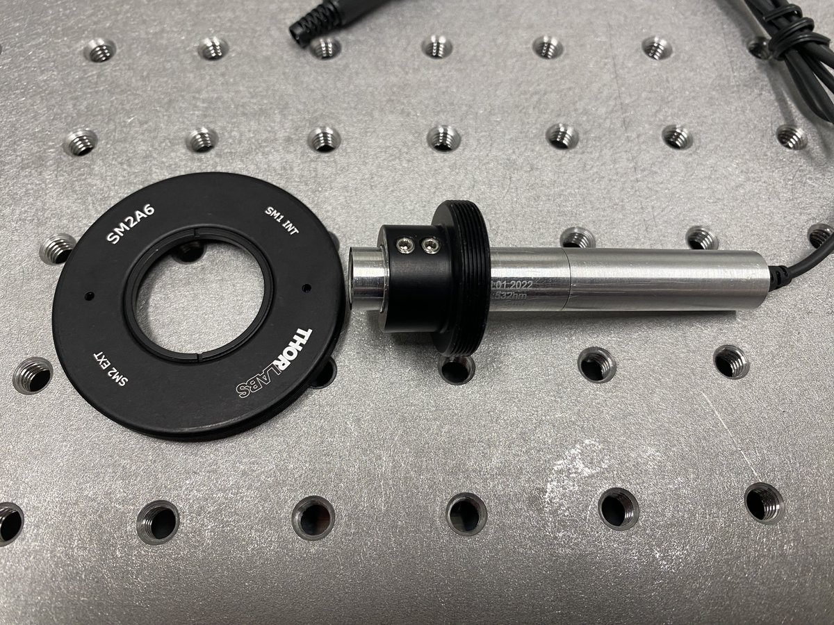
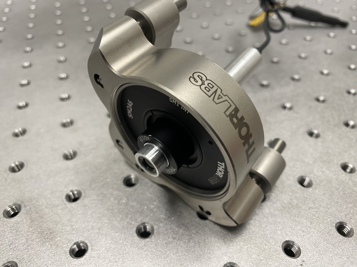
6/34 Alignment laser
1 x LDS5
1 x CPS532
1 x AD11F
1 x SM2A6
1 x SM1RR
1 x POLARIS-K2T2
2 x POLARIS-LN1
1 x PLS-P605/M
1 x RSA90/M
1 x POLARIS-SCA25/M
This 532-nm laser will define a perfectly straight line parallel to the breadboard– the optical axis of our system.
1 x LDS5
1 x CPS532
1 x AD11F
1 x SM2A6
1 x SM1RR
1 x POLARIS-K2T2
2 x POLARIS-LN1
1 x PLS-P605/M
1 x RSA90/M
1 x POLARIS-SCA25/M
This 532-nm laser will define a perfectly straight line parallel to the breadboard– the optical axis of our system.
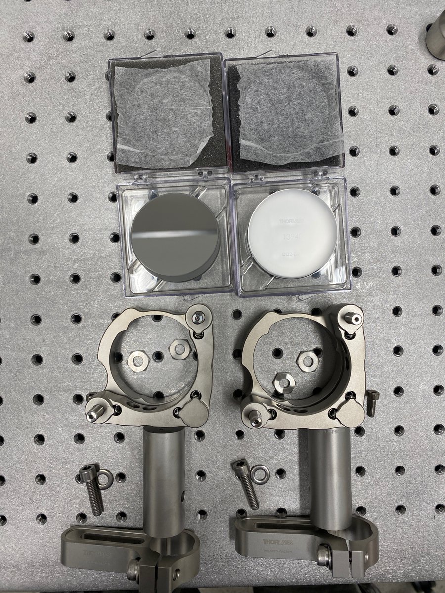
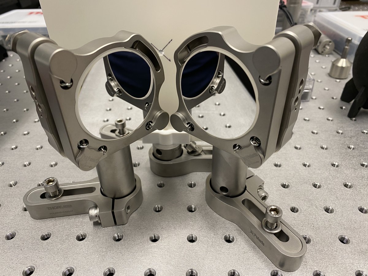
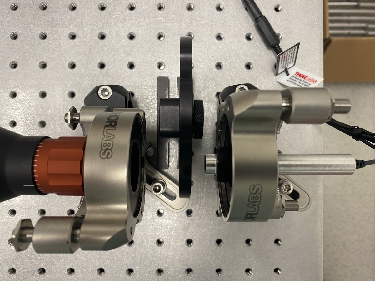
7/34 Beam steering mirrors
2 x BB2-E02
2 x POLARIS-K2S2
4 x POLARIS-LN1
2 x PLS-P605/M
2 x POLARIS-CA25/M
The alignment laser is meant to be moveable, but you have to realign it to the optical path (typically defined by a lens). These mirrors give you 4 DOFs to do so.
2 x BB2-E02
2 x POLARIS-K2S2
4 x POLARIS-LN1
2 x PLS-P605/M
2 x POLARIS-CA25/M
The alignment laser is meant to be moveable, but you have to realign it to the optical path (typically defined by a lens). These mirrors give you 4 DOFs to do so.
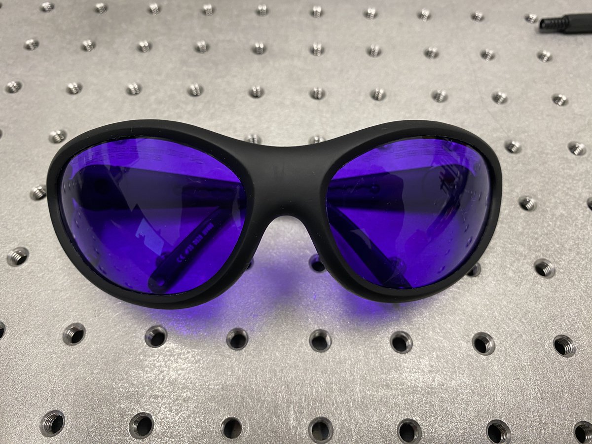
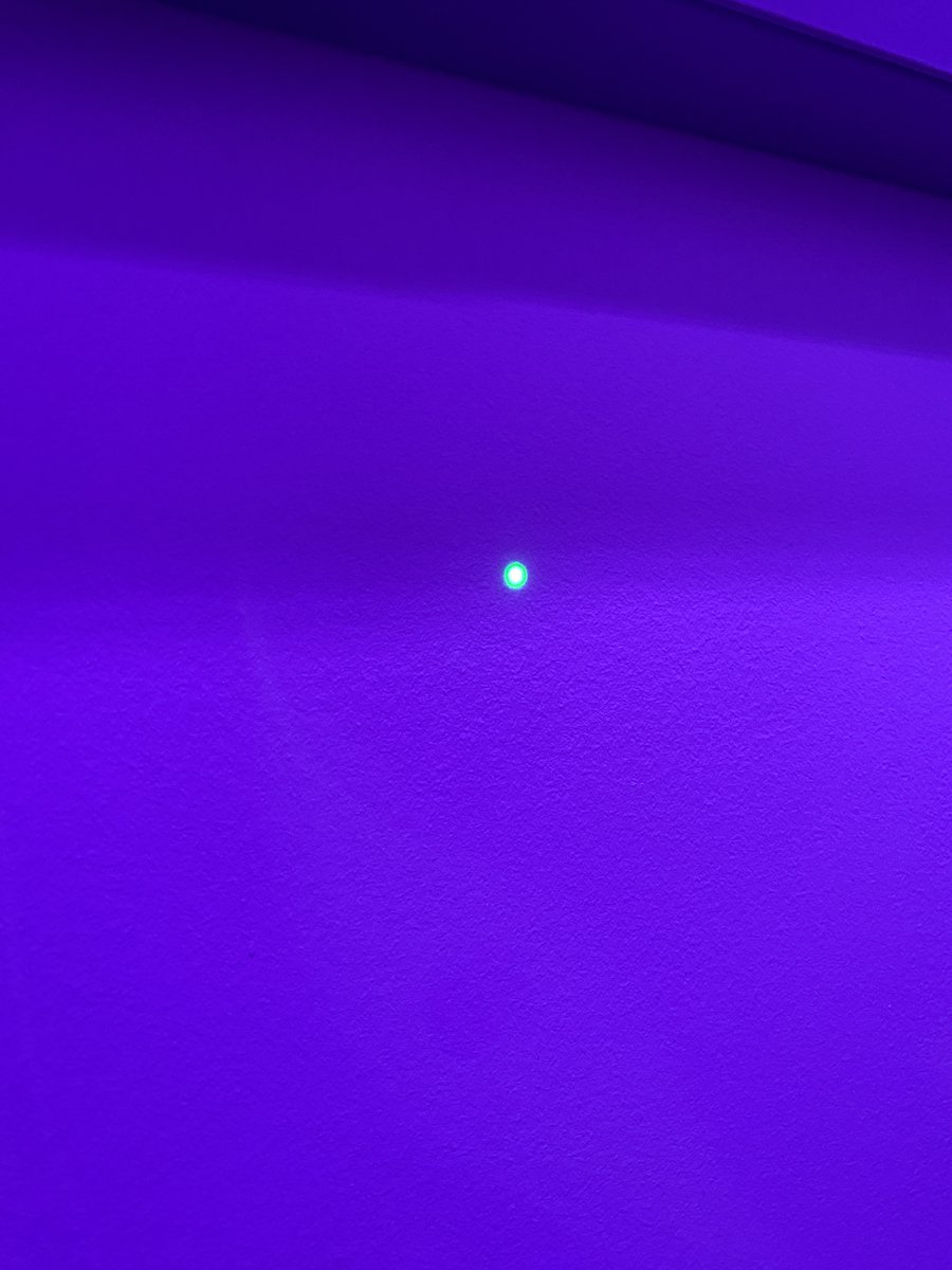
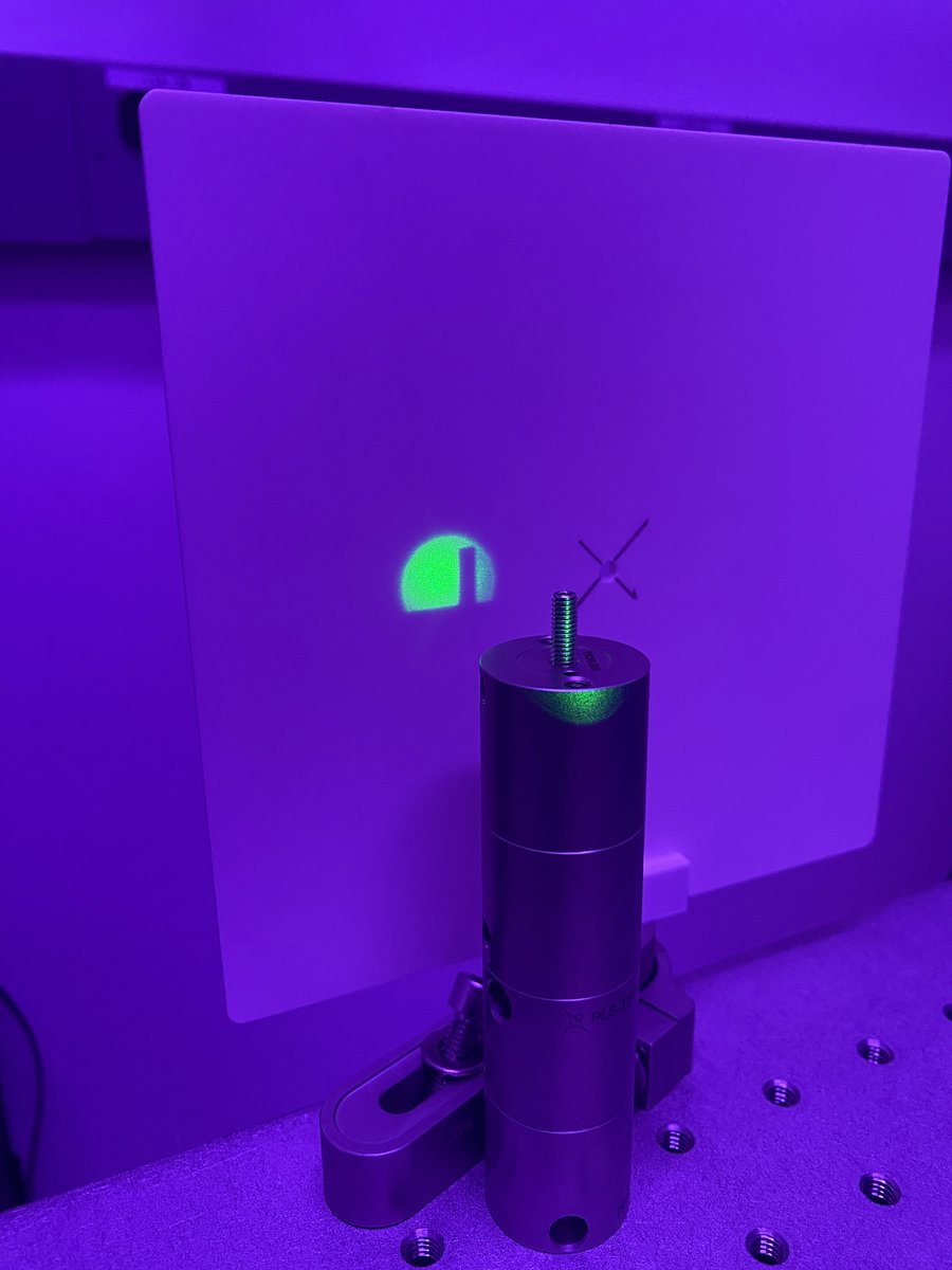
8/34 Turn your 532-nm laser on! I recommend a pair of LG15B laser safety glasses to comfortably view the laser scatter off of the viewing screen or a white wall.
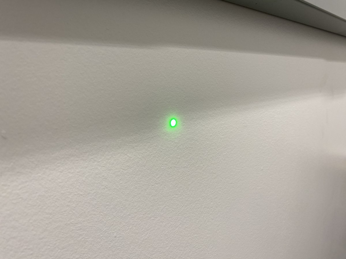
9/34 Try to roughly position the laser so that it runs parallel to a path of threads along the breadboard- this will help make the horizontal alignment tool more functional in the next steps. Use the viewing screen to trace the beam path.
10/34 Clamp down the laser to the breadboard. Using the Alignment Crane protocol (parts and steps listed here:
https://twitter.com/TanFad/status/1559187220291919874?s=20&t=LYYlG1bXE771GOxVSNx2Og), attach the alignment laser post to the alignment crane. Then detach the post from the table.
11/34 You should have *just* enough post height to fit a RS50/M clamp and the alignment crane post clamp if you’re planning on the beam to be 100 mm off the breadboard. Don’t forget to add the RS50/M clamp to the post before bolting down– this is important for cross-bracing.
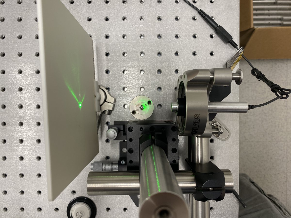
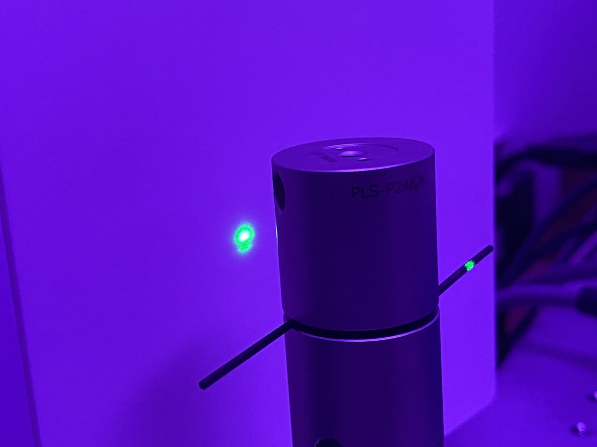
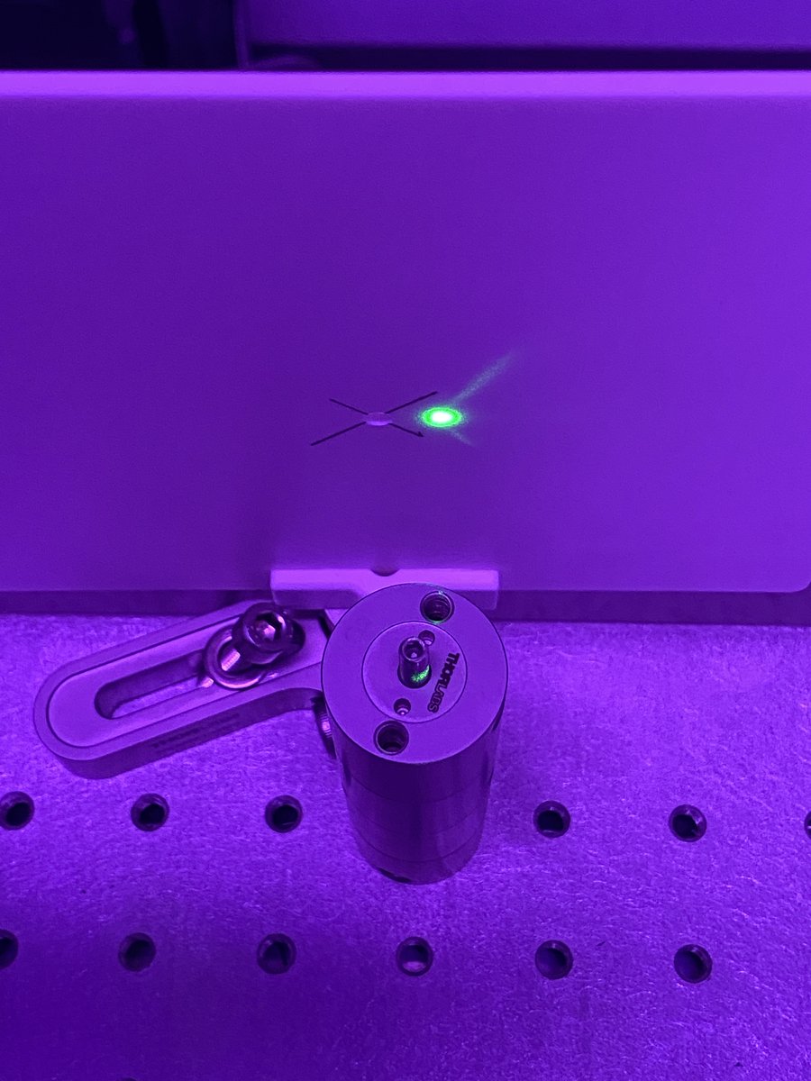
12/34 Screw the horizontal alignment tool in a thread as close to the alignment laser as possible without touching the laser or other components. Using the shadow of the tool as a reference, translate the beam with the alignment crane until the shadow is horizontally centered.
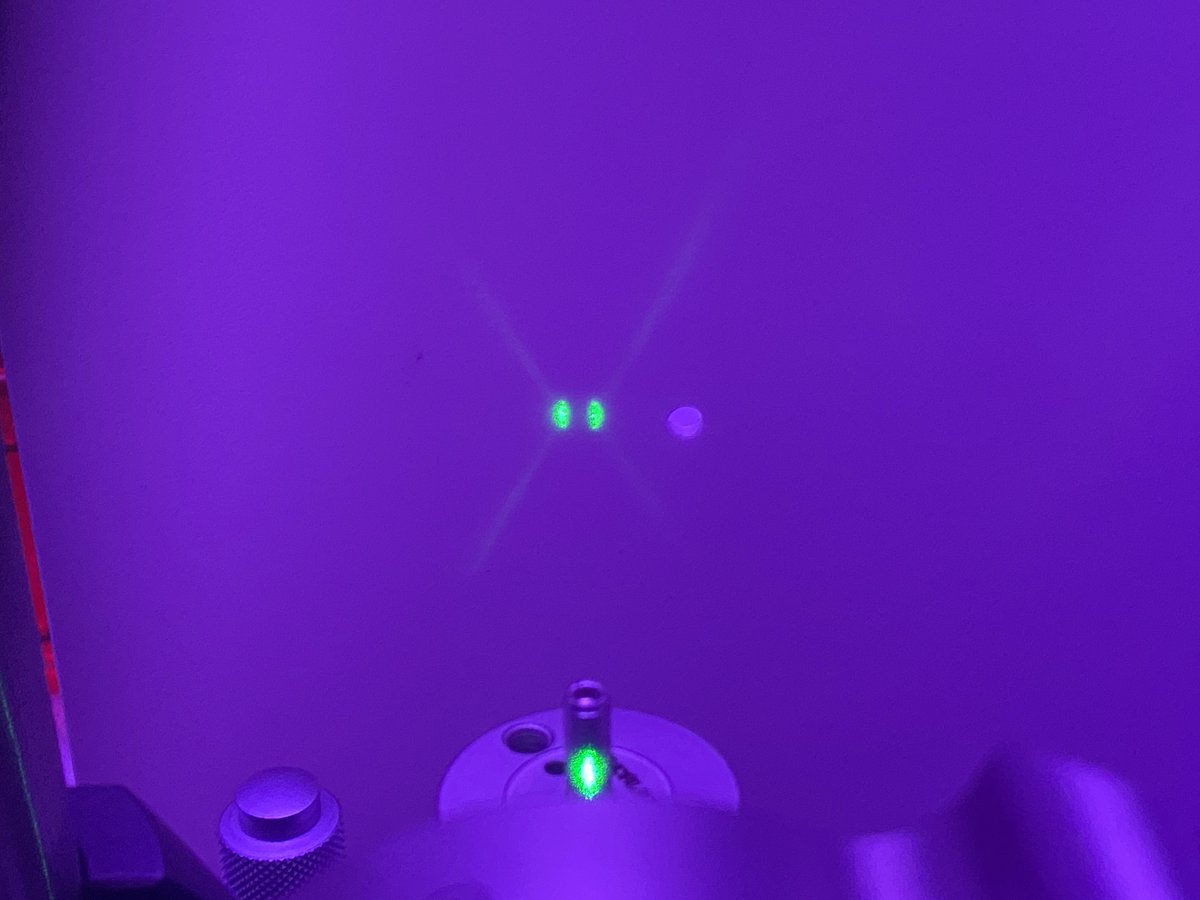
13/34 Replace the horizontal tool with the vertical tool. Translate the beam vertically with the alignment crane until the shadow of the vertical tool is centered on the beam.
14/34 Move the horizontal tool as far away from the laser as possible while still being on the breadboard. The farther you move it, the more accurate your alignment will be!
15/34 Using the angular adjustment bolts on the Polaris mount, adjust the vertical angle of the laser until it is centered about the vertical tool. Longer distances matter– if your error is +/- 1 mm at a distance of 1 m from the laser, your angular error is only about +/- 0.06º!
16/34 Repeat steps 15-16 with the horizontal alignment tool.
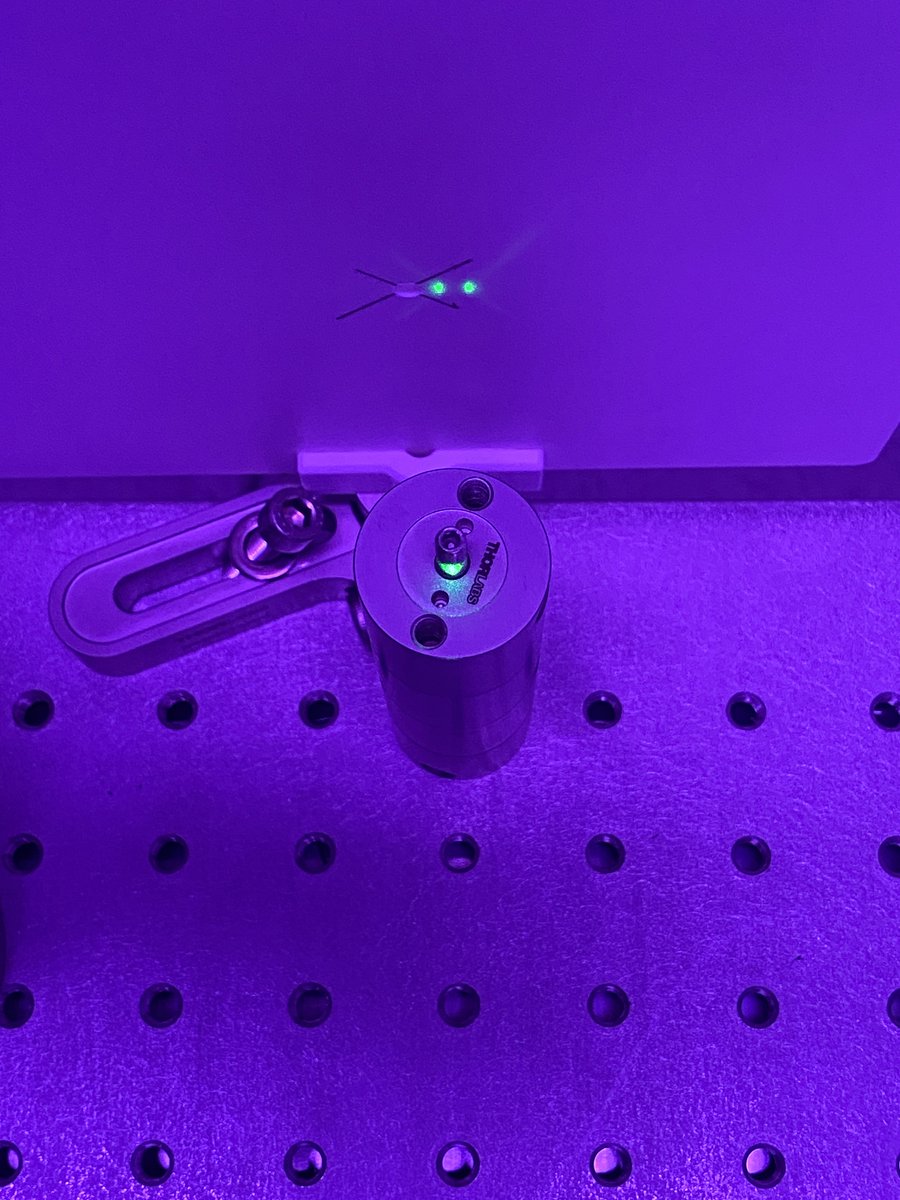
17/34 Move the vertical and horizontal alignment tools back to right in front of the laser. You’ll notice that the translational alignment is no longer how you left it! Translate the beam horizontally and vertically until it’s back in alignment.
18/34 Repeat steps 12-17 as many times as necessary to get the far-field and near-field beam to agree with the alignment tools. You’ll notice that after each iteration, the misalignment becomes less and less severe, indicating that you’re converging on the ideal optical axis.
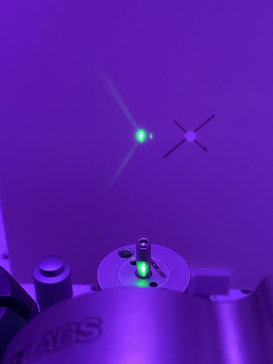
19/34 Transfer possession of the alignment laser from the alignment crane to the optical table. Oh no, your beam is misaligned (this is normal). Don’t disassemble your crane just yet. Take note of the misalignment (far and short field) and transfer possession back to the crane.
20/34 Transferring ownership is never perfect- but it *is* predictably imperfect. This means that you can offset the beam alignment while the laser is still attached to the crane so that the transfer is your final adjustment.
21/34 Tighten the lock nuts on the Polaris mount to lock the angular adjustments in place. Congratulations, your laser now defines a convenient optical axis!
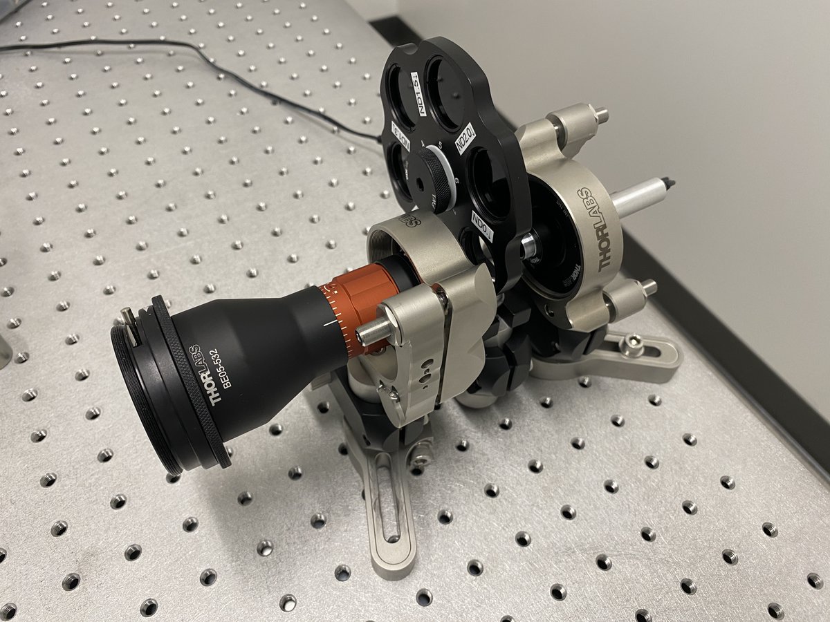
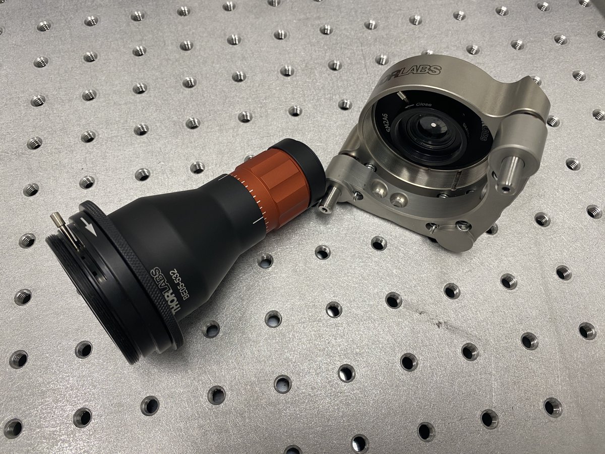
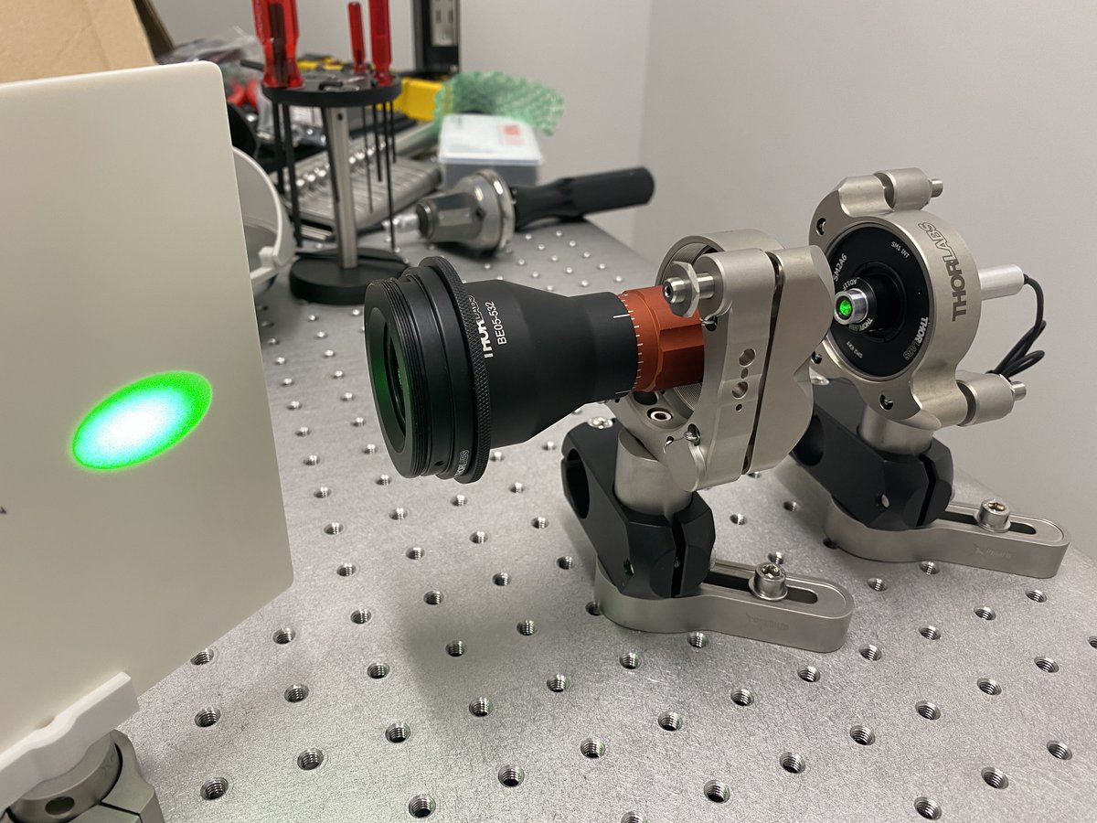
22/34 Beam expander
- 1 x SM1D12
- 1 x BE05-532
- 1 x SM2D25
- 1 x SM2A30
- 1 x POLARIS-K2T2
- 2 x POLARIS-LN1
- 1 x PLS-P605/M
- 1 x RSA90/M
- 1 x POLARIS-SCA25/M
The beam expander gives you more flexibility with the beam diameter, and it allows you to collimate your beam.
- 1 x SM1D12
- 1 x BE05-532
- 1 x SM2D25
- 1 x SM2A30
- 1 x POLARIS-K2T2
- 2 x POLARIS-LN1
- 1 x PLS-P605/M
- 1 x RSA90/M
- 1 x POLARIS-SCA25/M
The beam expander gives you more flexibility with the beam diameter, and it allows you to collimate your beam.
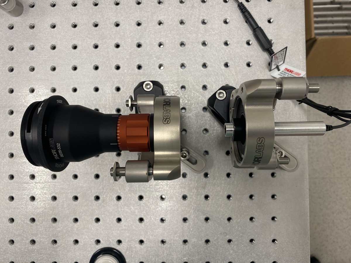
23/34 Place the beam expander close to the optical axis. Be sure to leave enough room between the laser and the expander for the filter wheel!
24/34 Repeat the alignment crane protocol with the beam expander. Use the same horizontal and vertical alignment tools to center the beam expander along the optical axis. Use the irises to check that the center of the beam is on each tool, in both the far and near fields.
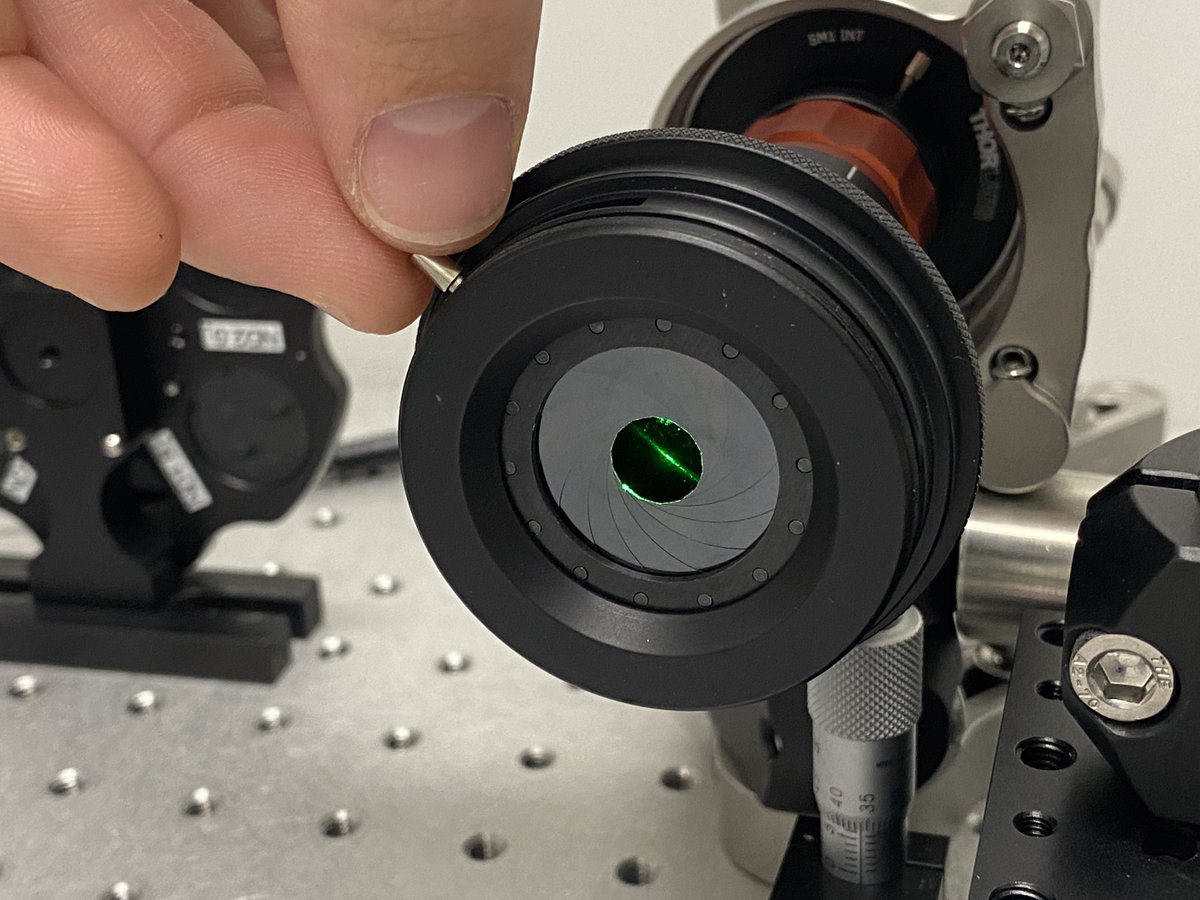
25/34 Your beam expander now agrees with your alignment laser about where the optical axis is- awesome! You’re almost done.
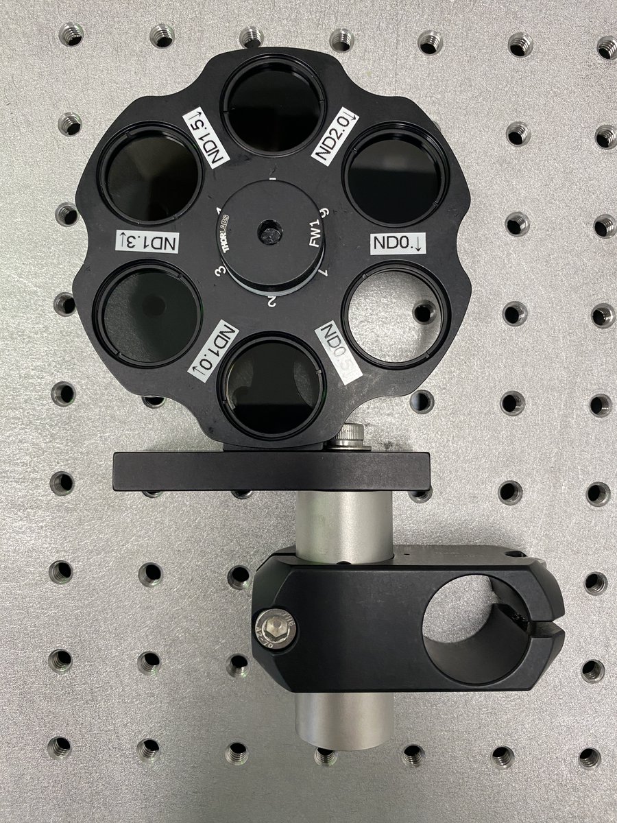
26/34 ND filter wheel
- 1 x FW1AND (or choose your own ND filters)
- 1 x PLS-P605/M
- 1 x RSA90/M
The filter wheel is nice to modulate the intensity of the beam without needing glasses. This is especially useful if you plan on sending the light to a detector.
- 1 x FW1AND (or choose your own ND filters)
- 1 x PLS-P605/M
- 1 x RSA90/M
The filter wheel is nice to modulate the intensity of the beam without needing glasses. This is especially useful if you plan on sending the light to a detector.
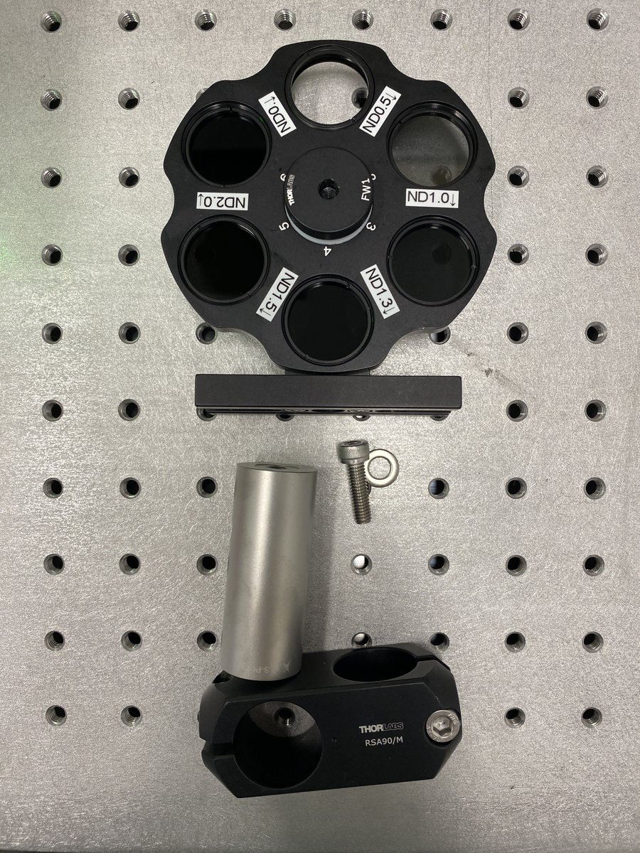
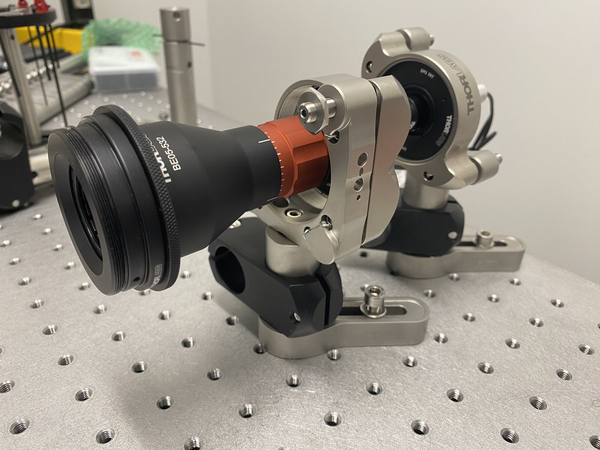
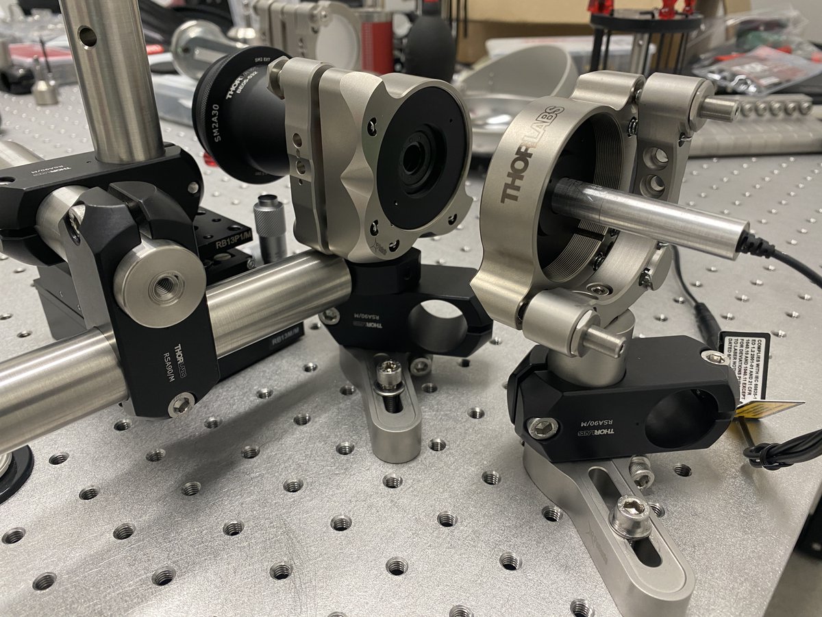
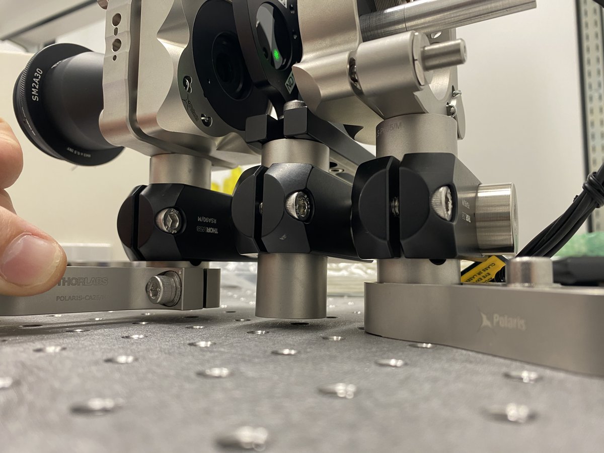
27/34 Cross-brace
- 1 x RS150/M
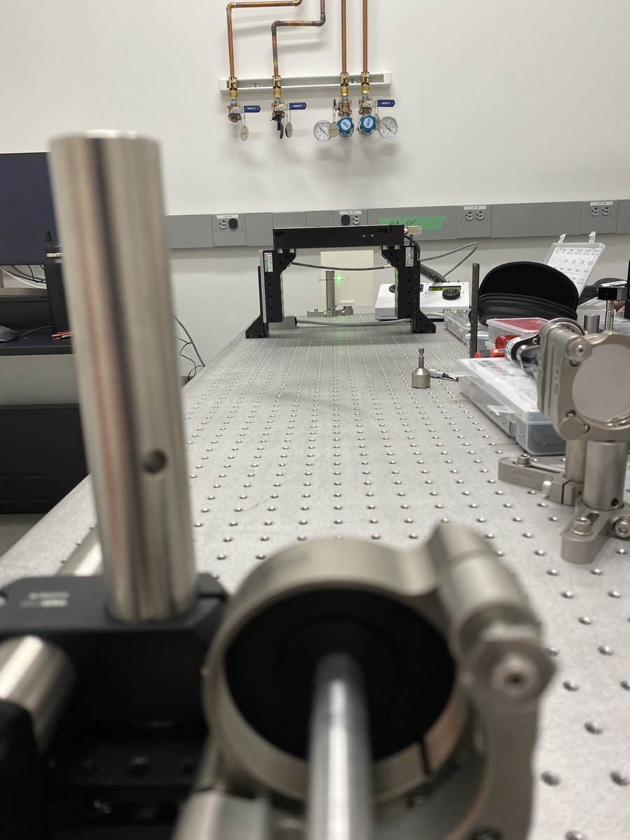
Remember those right angle brackets? Here’s where they come in. Put the filter wheel in between the laser and the expander, then slide the cross-brace through all three brackets.
- 1 x RS150/M
Remember those right angle brackets? Here’s where they come in. Put the filter wheel in between the laser and the expander, then slide the cross-brace through all three brackets.
28/34 Raise the cross brace and the three brackets until they are slightly above the clamping arms. Tighten the bolts on the bracket attached to the laser post first, then the bracket bolts on the expander.
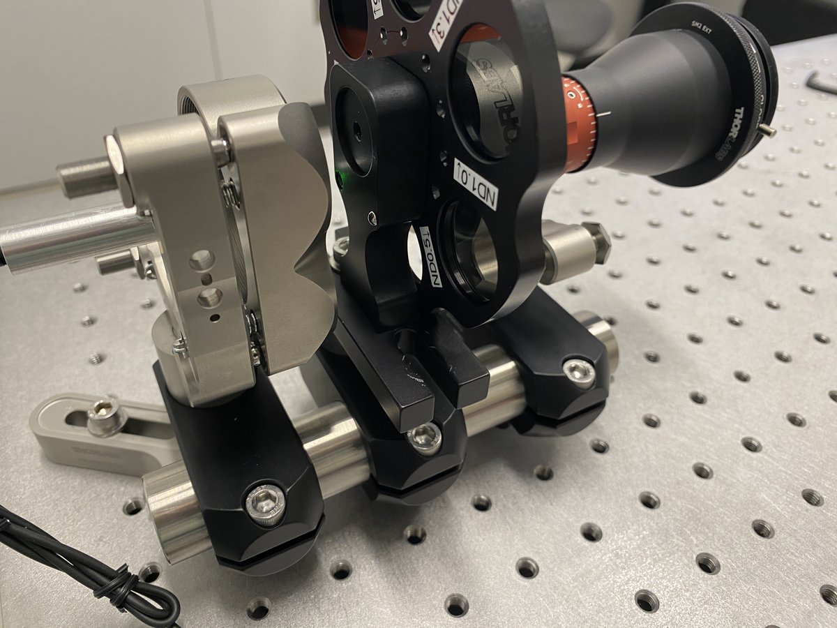
29/34 Before tightening the filter wheel bracket, rotate the filter wheel so that the back reflections off of an ND filter line up with the laser. This ensures that the filters won’t cause any lateral translation of the beam from refraction.
30/34 Raise the filter post off the breadboard, then tighten its bracket. Finally, loosen the clamping arm around the expander post. You now have a cross-braced alignment assembly with one point of contact, à la @JLazzariDean/@AndrewGYork
https://twitter.com/JLazzariDean/status/1567680867002363905?s=20&t=qCBX2RjQlXBpkjMGVgpwdw
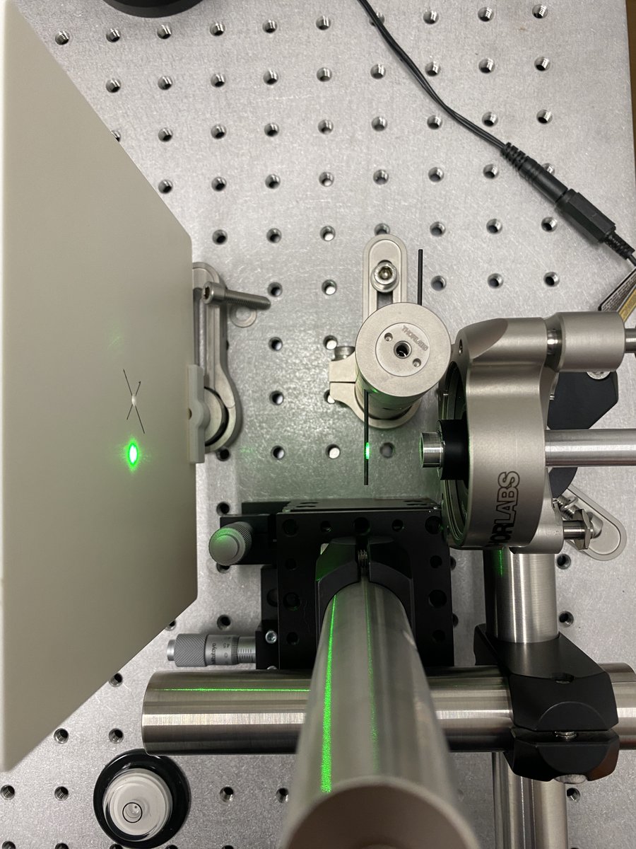
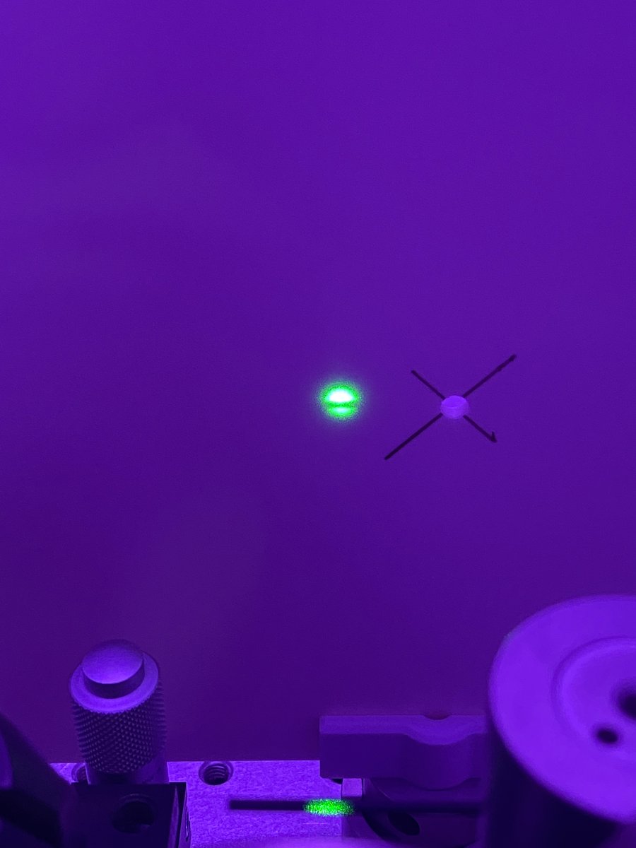
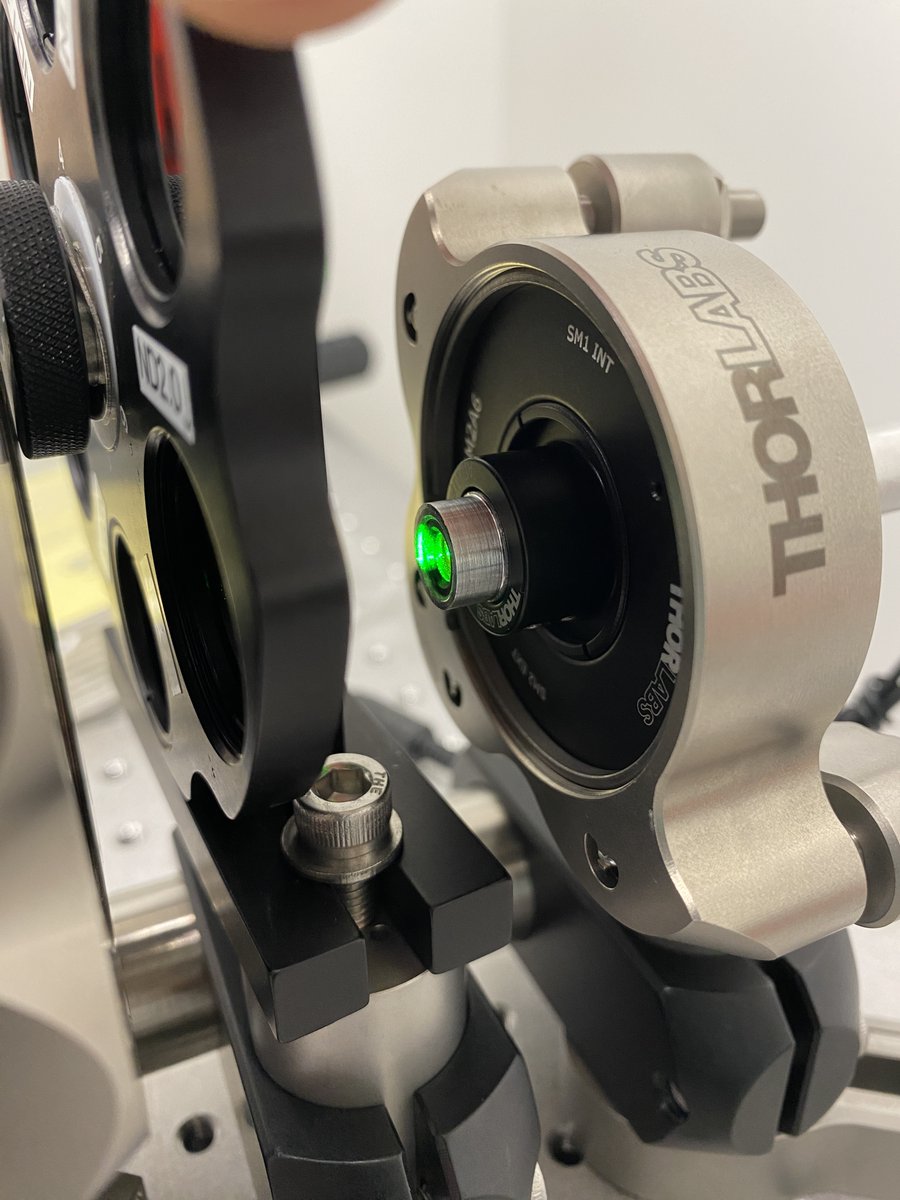
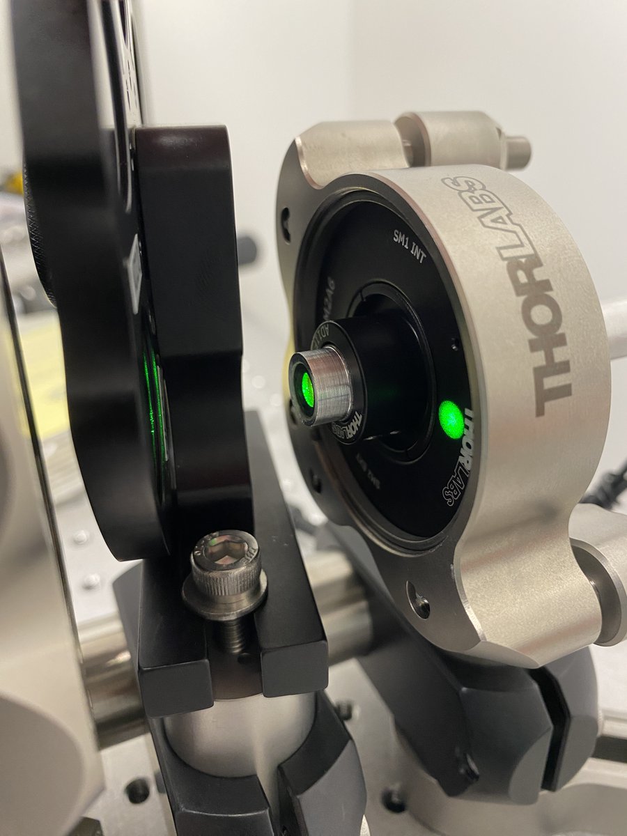
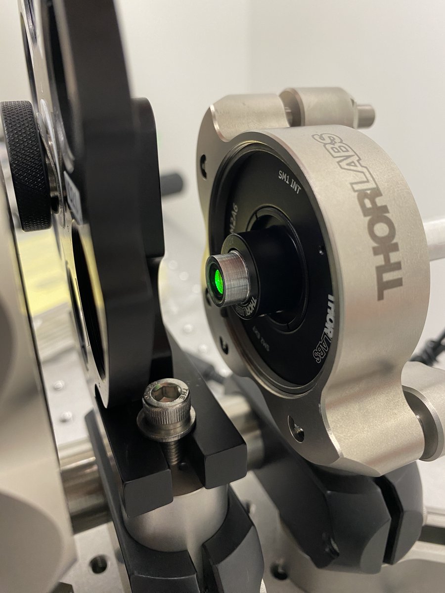
31/34 Align the viewing screen so that its hole is centered about the beam height. This allows the alignment laser to pass through the screen while looking at back reflections of lenses.
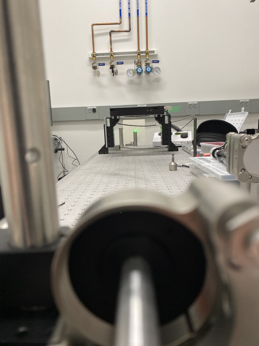
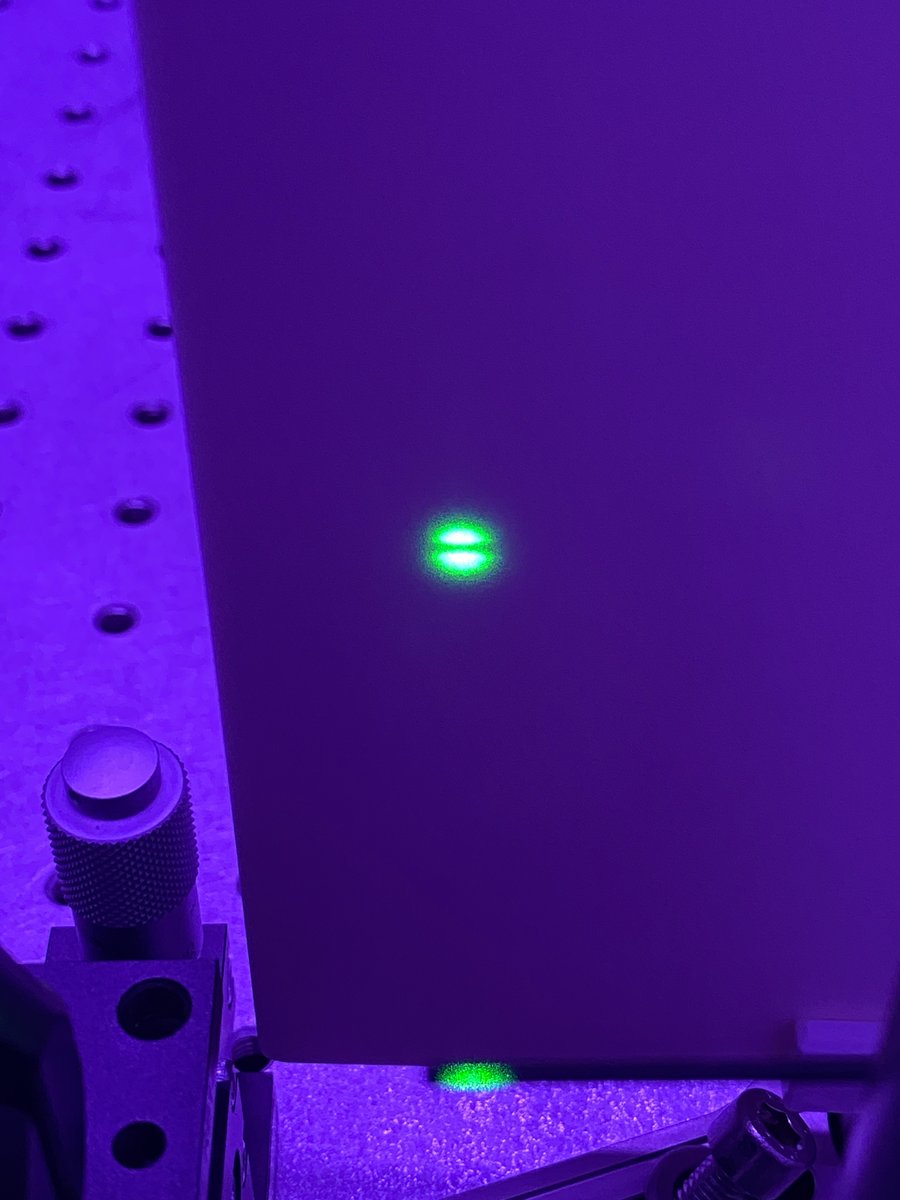
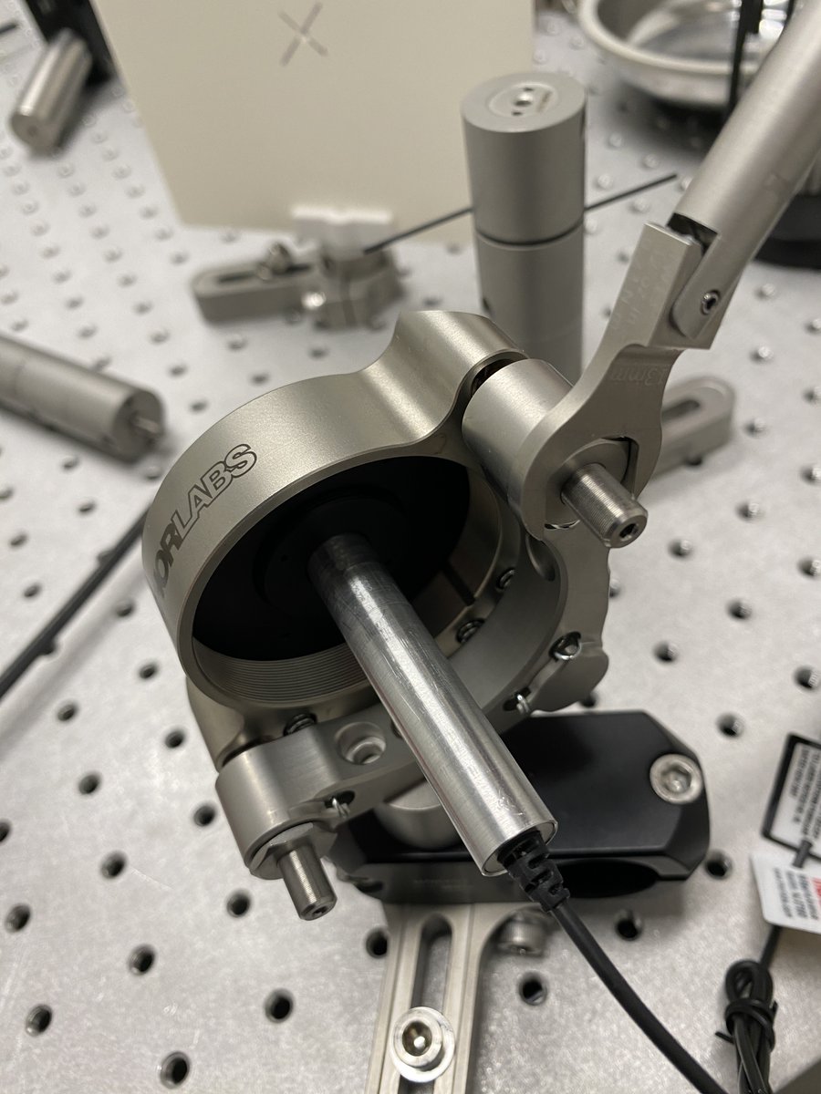
32/34 To collimate your beam, place a mirror at the far end of the table. This is a quick way to double your optical path length. Make sure that the path length over which you check collimation is greater than the path length of your system!
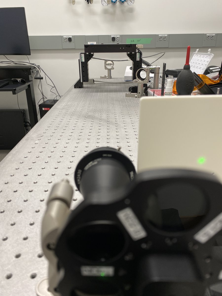
33/34 Place the screen next to the expander. Adjust the collimation collar on the expander until the beam is the same diameter in the near and far fields. Also check that the beam hasn’t focused somewhere in the middle of your path! Tighten the lock screw on the collar.
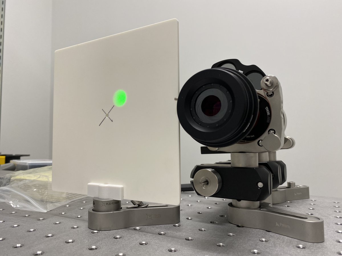
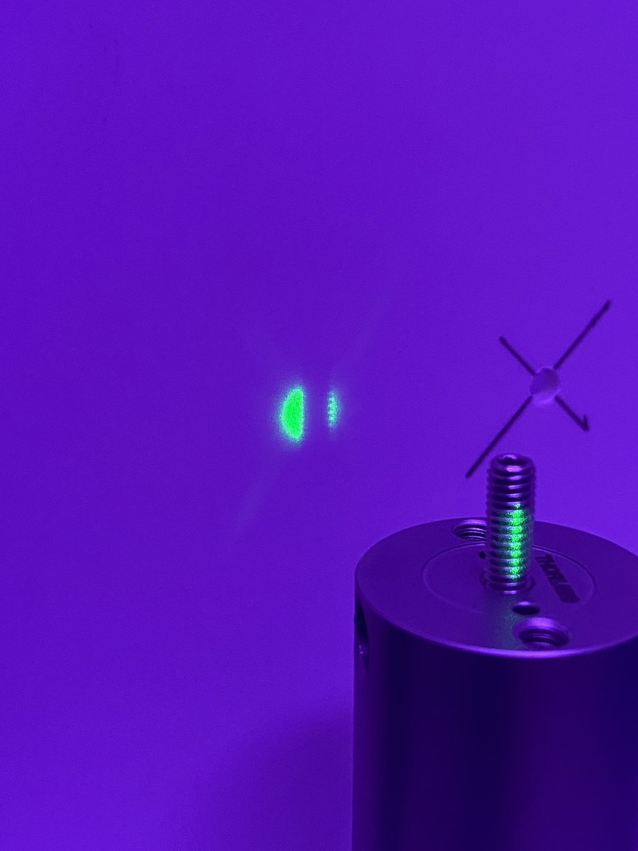
34/34 You’re done! Congratulations, you have a reusable tool that can check for alignment of every optical component in your system. Here is one example of the alignment laser being used to align an objective lens with a tube lens. Check out the back reflections on the screen!
Thanks to @AndrewGYork for teaching me how to build an alignment laser assembly!
• • •
Missing some Tweet in this thread? You can try to
force a refresh