Assembled the (v0.6) AKL-AV1 prototype! Characterization results in this thread.

For those of you just tuning in, the AV1 is an open hardware 1.5 GHz class, high impedance, solder-in, single ended active voltage probe (5MΩ || 350 fF, 10x attenuation) that runs on 5.5V DC.
First step is low frequency trimming. This adjusts the DC path (OPA210) and AC path (BUF802) to have the same gain.

Seen here before and after.
Next, high frequency trimming. The JFET amplifier stage has a 2.4 pF input capacitance so to reduce loading on the DUT there's a 5:1 R-C divider in front of it.

Shunt path is a 1MΩ terminator across the BUF802, series path is 4MΩ in parallel with a 250 - 750 fF trim cap.
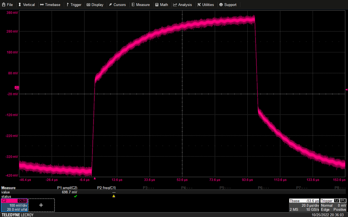
All trimmed up. While it's still on the fixture, I swapped out the function generator for one of Leo Bodnar's fast pulse generators.

Rise time (including cable losses) is almost identical to my 1.5 GHz LeCroy ZS1500. A little bit of overshoot/ring but way better than last rev.
Soldered onto the PRBS generator board for some eye pattern work on a PRBS-31 at 1.25 Gbps.

Pretty good. A tiny bit of overshoot but way less than the previous revision (Mini-Circuits LFCG, vs the 4th order discrete Bessel used here).
Next up, VNA S21 response of the probe head (no cable, but including losses of the SMA-SMPM adapter and PCF200 fixture).

Better than +/- 0.2 dB flatness from DC to 500 MHz, +/- 0.4 dB to 1 GHz. But then it falls off faster than intended.
Design goal was for -3 dB BW of 1.8 GHz on the filter and system bandwidth in the 1.5 to 2.0 GHz range. We fell slightly short at 1.32.

The inductors I'm using are performing slightly worse than sim in another design, so I might try tweaking their values slightly.
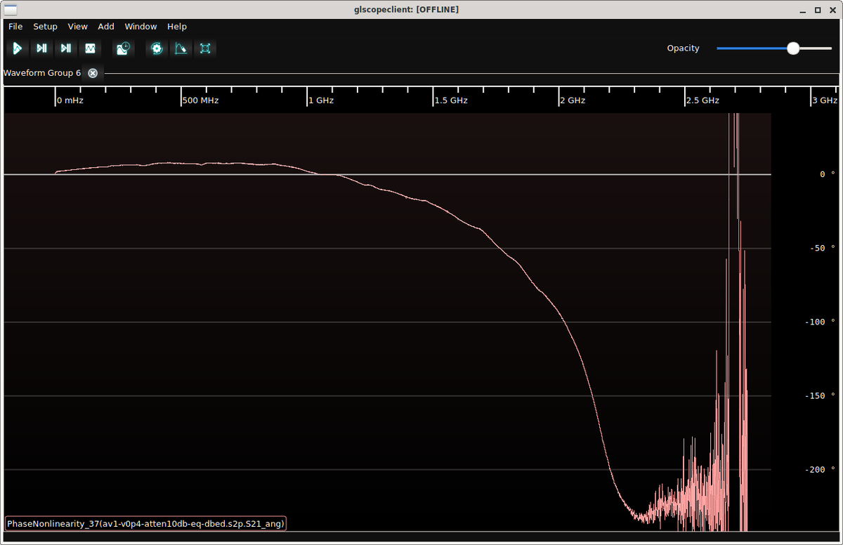
But I have to be careful because of how good the phase response is with the current filter. Within +/- 10 degrees of perfectly linear from DC to 2 GHz.
By comparison, the previous rev using the Mini-Circuits filter (which isn't optimized for phase linearity in the transition region) is a whopping 93 degrees off a linear response at 2 GHz.
This phase nonlinearity clearly shows up in the eye pattern of the old v0.4 probe: the rise time is a bit slower, then there's a big overshoot as the delayed second harmonic of the edge hits.
Comparing S21 magnitude of v0.6 (red) and v0.4 (blue), we see that v0.4 has significantly higher BW (about 500 MHz more).

So if I can shift the cutoff frequency of the new Bessel filter a bit right without sacrificing linearity, I'll have a winner.
In any case, I'm now confident that the v0.6 board spin is basically final.

There will probably be BOM tweaks to the filter components to try and squeeze out a bit more BW, but I'm not seeing any reason to mess with the layout.

• • •

Missing some Tweet in this thread? You can try to force a refresh
 

Keep Current with Andrew Zonenberg @azonenberg@ioc.exchange

Andrew Zonenberg @azonenberg@ioc.exchange Profile picture

Stay in touch and get notified when new unrolls are available from this author!

Read all threads

This Thread may be Removed Anytime!

PDF

Twitter may remove this content at anytime! Save it as PDF for later use!

Try unrolling a thread yourself!

how to unroll video
  1. Follow @ThreadReaderApp to mention us!

  2. From a Twitter thread mention us with a keyword "unroll"
@threadreaderapp unroll

Practice here first or read more on our help page!

More from @azonenberg

Aug 27, 2022
Friend of mine has been troubleshooting some major EMC problems for a while so I decided to grace the project with a song. Here's my latest draft. Suggestions?

"The Sound Of Crosstalk"
(to the tune of The Sound Of Silence)
Hello crosstalk, my old friend
I've come to fight with you again
Because a field line softly creeping
Left microstrip while I was testing
And the waveform I was sending through my board
Still remains... it is the sound of crosstalk
In restless days I probed alone
Nearby striplines, coupled tones
'Neath the halo of a H-field loop
I turned my specan to the board and hoped

When my graphs were stabbed
By the peak of a coupled tone
Standing alone
It was the sound of crosstalk
Read 6 tweets
Jul 26, 2022
This is how you're supposed to simulate a circuit with a resistor in it, right?

Device is a R20L125 rod resistor from ResNet Microwave (electrotechnik.com/pdf/ROD.pdf). I'm interested in simulating the flatness of a probe using it as an attenuator.

Vendor doesn't publish S-params.
This model is mostly based on guesswork as I don't have a lot of details from their datasheet on internal construction (e.g. metal layer thicknesses).

But as a first order estimate, I calculate 7-10 fF shunt capacitance depending on frequency.
I asked for samples, and they're going to be sending me two 50-ohm devices.

My hope is that with some EM simulation plus characterization of the 50-ohm parts, I can extrapolate to see how a 450-ohm device behaves.
Read 6 tweets
Mar 22, 2022
I've had an HP LaserJet all-in-one printer in my home office for a couple of years now. I finally ran out of black toner and had to swap the cartridge out.

The box had this cool anti-counterfeiting seal on it, which changes appearance as you tilt it. Let's take a closer look!
There's a barcode and QR code that seem to be printed using fairly ordinary black ink on paper, and then there's a special insert (the blue area) where Magic(tm) happens.

Let's look at the "toner" microprint area.
As you tilt the label, the six little balls rotate while the rest of the graphic remains fairly constant in appearance.
Read 11 tweets
Jan 30, 2022
Open offer: If anyone sends me one of these (or any other similar audiophool products) I'll do a full signal and power integrity workup on it. And send it back after if you want.

I'd love to see how awful that "low noise" power rail really is.
Oh, and of course these geniuses are throwing a fancy TCXO on the board to get "low jitter" clocking.

... except the actual NVMe interface is clocked by the PCIe refclk. Which is spread spectrum modulated on most motherboards.
So even if the flash controller's internal PLL had good enough jitter characteristics that a better reference would improve it, at most you'll improve setup/hold margins between the controller and the NAND die.

Which *totally* helps with audio quality.
Read 4 tweets
Jan 29, 2022
Sample of the green corrosion (no white stuff present) being sent off for EDS.

I expect to see lots of copper but curious what the other peaks will be. Chlorine seems plausible.
Also, I really need to get a polarizer or something on this scope... the glare with shiny surfaces like this carbon tape is pretty extreme.
Sampled another region of slightly transparent yellow stuff.

As long as I'm sending stuff out for analysis might as well do a second specimen.
Read 4 tweets
Jan 29, 2022
Many of my followers, or anyone who works with higher end @TeledyneLecroy oscilloscopes, are probably familiar with the PCF200 test fixture.

It's a small piece of low loss PCB with two CPWG thru lines, one with a .1" header and the other with a clip for solder-in probes tips.
@TeledyneLecroy The intended use is de-skewing of different probes: you terminate one end of the fixture, drive a fast edge into the other end, then place each probe at the same point on the fixture and adjust skew until you see the edge at the same point on the scope display.
They're sold individually for a ridiculous price but nobody buys them because any time you buy a LeCroy differential probe you get one thrown in the accessory kit. Even if you break one somehow you've probably got a ton of spares. I have four in my lab at the moment I think.
Read 12 tweets

Did Thread Reader help you today?

Support us! We are indie developers!


This site is made by just two indie developers on a laptop doing marketing, support and development! Read more about the story.

Become a Premium Member ($3/month or $30/year) and get exclusive features!

Become Premium

Don't want to be a Premium member but still want to support us?

Make a small donation by buying us coffee ($5) or help with server cost ($10)

Donate via Paypal

Or Donate anonymously using crypto!

Ethereum

0xfe58350B80634f60Fa6Dc149a72b4DFbc17D341E copy

Bitcoin

3ATGMxNzCUFzxpMCHL5sWSt4DVtS8UqXpi copy

Thank you for your support!

Follow Us!

:(