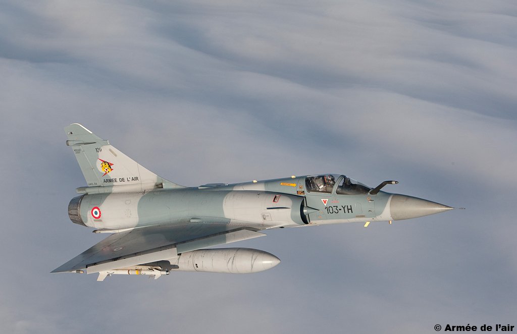
MiG-23 air intakes design.
Whenever somebody brings up the MiG-23 intakes, there is always that person who just has to say "yeah, it's just a copy of the F-4 Phantom intakes, they even copied the number of boundary-layer bleed holes and those struts that are meant to cut the...
Whenever somebody brings up the MiG-23 intakes, there is always that person who just has to say "yeah, it's just a copy of the F-4 Phantom intakes, they even copied the number of boundary-layer bleed holes and those struts that are meant to cut the...
...arresting net to allow the canopies to open". And I, as any self respecting бutt-hurt MiG-23 fan-boy, will automatically deny it, while tears run down my cheeks.
In truth, the MiG-23's variable intake ramp system is indeed evidently based on that of the F-4's. Despite it...
In truth, the MiG-23's variable intake ramp system is indeed evidently based on that of the F-4's. Despite it...
...being a "copy", in my opinion, it also has enough differentiating features that make it worth a look at, if you are interested in aero-engineering.
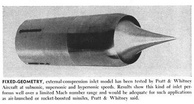
First, how are the similar? Both are variable-geometry supersonic intakes, with vertical 2D ramps, with external compression...
First, how are the similar? Both are variable-geometry supersonic intakes, with vertical 2D ramps, with external compression...
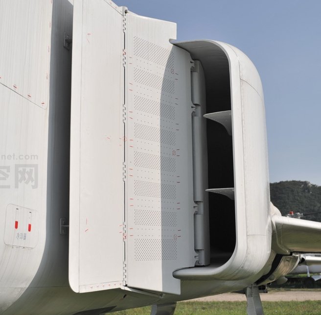
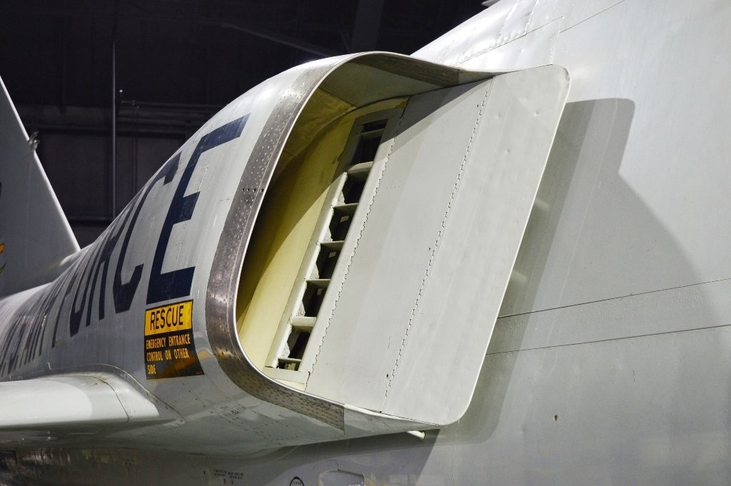
and with boundary layer bleed holes on the movable portion of the ramps. They also have the same mode of venting said boundary layer, through two chutes top and bottom of the ramps. They also have those sharp struts between the splitter-plate and fuselage. I'll add the J-8II... 
...to this discussion as a bonus. Regarding the struts, I wonder if the Warsaw Pact countries also found the useful. dr-peter-horn.homepage.t-online.de/htm/Win_Inf_AT…


So, plenty of similarities. However, there are also some subtle differences.
Shock waves. The MiG-23’s intakes at the design Mach number (M = 2.35 according to the manual) will each generate 4 shock waves (3 obliques and 1 normal) as seen in the picture from "Практическая..
Shock waves. The MiG-23’s intakes at the design Mach number (M = 2.35 according to the manual) will each generate 4 shock waves (3 obliques and 1 normal) as seen in the picture from "Практическая..
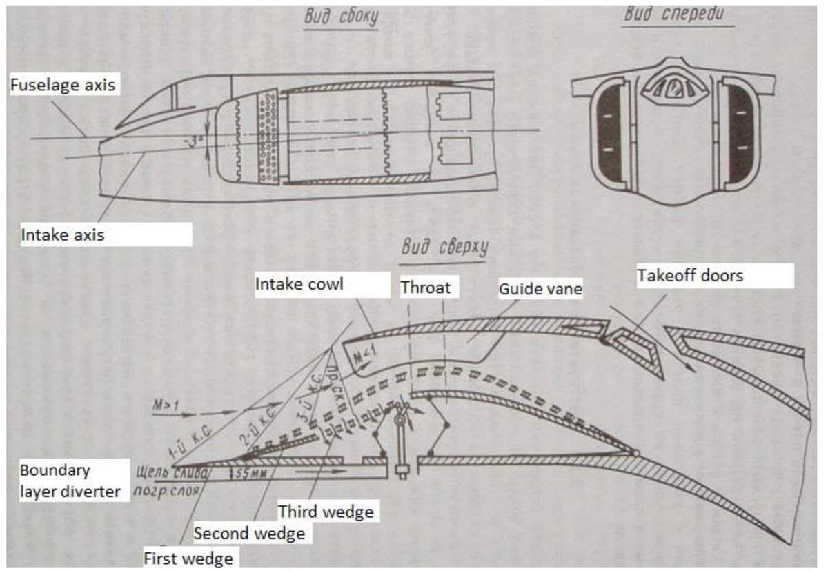
...аэродинамика самолета МиГ-23МЛ и МиГ-23УБ - учебное пособие". The F-4’s intake will generate 3 shock waves (2 obliques and one normal). The use of more shocks to decelerate the flow would most likely give better pressure recovery (and hence higher thrust) at high Mach numbers.
This extra 3rd oblique shock wave is generated by a slight bend in the movable ramp. It is barely visible in photographs.
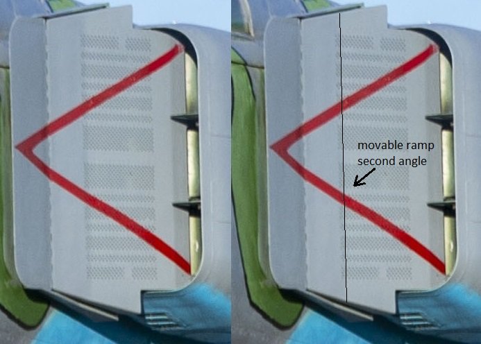
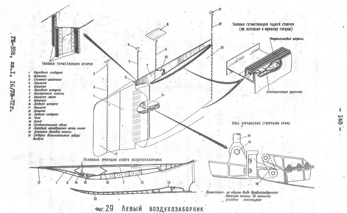
A detailed schematic of the mechanism can be found in the MiG-23M structural description book "Изделие 23М - Краткое описание и иструкция по технической эксплуатации ГК-358, Книга 1 - Самолёт и его системы" from 10th July 1972.
Intake cowl lips. The intake cowl lips on the MiG-23 are very sharp, in contrast, the F-4’s are a bit more rounded & cambered down to improve airflow at high AoA. Even though both these aircraft have slightly angled down intakes, ordinarily the F-4’s rounded & cambered intake...

...cowl lips would give it an advantage while flying at high AoA (and in subsonic cruise mode). The MiG-23’s sharp lips would be a problem with detached & uneven air flow at the compressor face. To solve this, the fighter versions of the MiG-23 have 2 horizontal guide vanes at...

...the entrance to even out the flow while at high AoA. The ground-attack version, MiG-23BN, lacks these guide vanes, and consequently suffers from compressor stalls at high AoA. The guide vane story is actually a bit more complicated. The initial design that was on the...
...MiG-23M/MF/MS and early Soviet MiG-23ML was found to be inadequate, and so late production MiG-23MLs had a longer & cambered lower intake guide vane. In Sergey Burdin's book "Истребитель МиГ-23. История, конструкция, вооружение, боевое применение, Минск: Харвест, 2002" we...

...read that during the MiG-23ML conversion to MiG-23MLD 23-18, one step, according to maintenance bulletin 23-1000BU, was to modify the intake guide vanes. These activities were carried out from May 1982 to May 1985. About 560 Soviet Air Force (VVS) aircraft were converted.
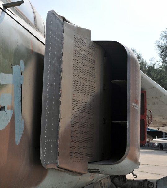
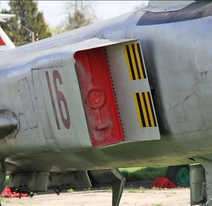
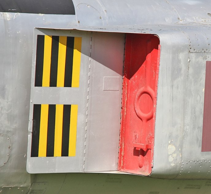
One last difference is the presence of side air-doors , that open up during high engine RPM & low speed modes, to compensate for the intakes being sized for high speeds, due to pressure difference. I don't know if the F-4 Phantom has similar doors. Maybe @heatloss1986 can help.
What do these facts tell us? Well the facts that the MiG-23 has very sharp intake cowl lips and a 4-shock-wave system are clear indicators, to me at least, that the Soviet designers were mostly concerned with high supersonic performance (max Mach and acceleration).
The thing is made to go fast, all else be damned! So while the F-4's intakes are also a high Mach design, the MiG-23's is optimized just a bit further in that direction, while I assume that the F-4's intakes also needed to consider low speed & high AoA for carrier operations.
The Soviets did indeed achieve their goal of making the MiG-23 capable of very high Mach. The MiG-23ML flight manual states at page 189 that a Mach number of 2.6 is achievable while armed with two R-23 missiles and the wings set at 72° sweep angle, in the stratosphere.


The third, less talked about design, is that of the Shenyang J-8II. Since the Chinese obtained a MIG-23 from Egypt, you would expect the J-8II’s intake to be a very close copy of the MiG-23’s, which it is.
china-defense.blogspot.com/2009/09/egypti…
china-defense.blogspot.com/2009/09/egypti…

But, it too has its own distinct features. As far as I can tell from photos the J-8II has a 3-shock system, like the F-4. It also has much more rounded intake cowl lips that the MiG-23 (particularly at the lower horizontal portion of the cowl). Does this mean that the Chinese...
...designers used the F-4 as inspiration, together with the MIG-23? No, just that these design changes more likely indicate that the J-8II’s engines were maybe less stall tolerant that the MiG-23’s, hence the need for more rounded cowl lips. Why use the 3-shock design? IDK.
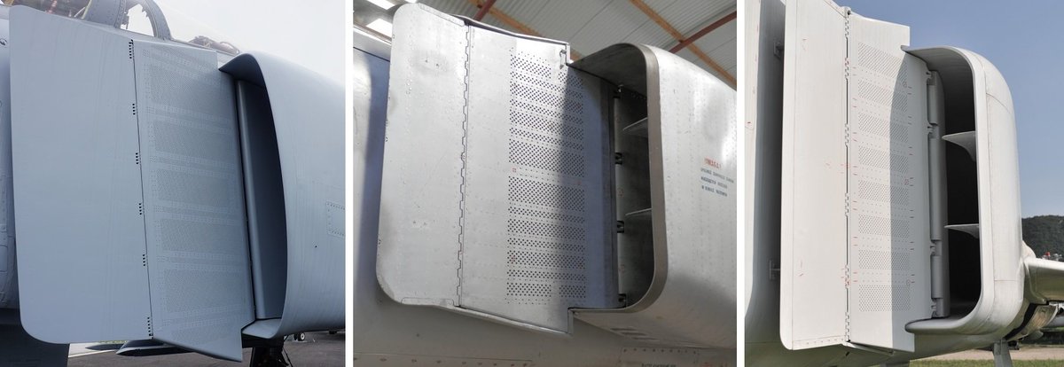
Regarding the "my friend counted the bleed holes on both, and they're the same number" story... well even a quick visual comparison proves this to be wrong. It is clear from the photos posted that the F-4 has many more holes. The interesting thing is that if you look at the...
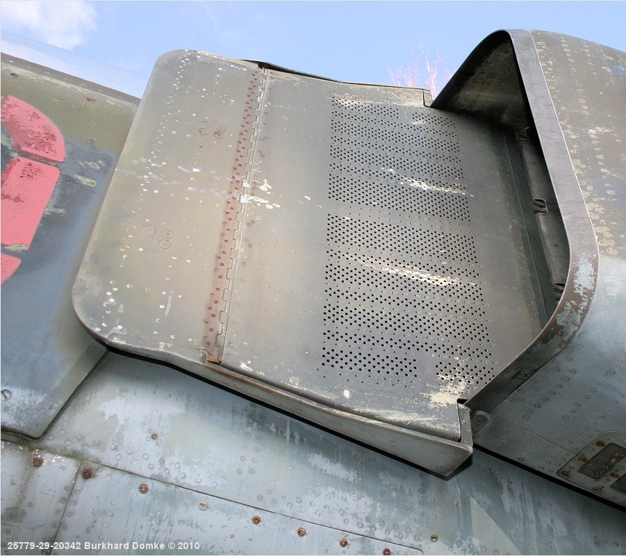

...MiG-23 prototypes you will notice that their bleed hole pattern is very different from the production models. So the production MiG-23’s hole pattern is different, but close to the F-4’s, but the MiG-23 prototypes had very different paterns. Which makes me wonder, if they...
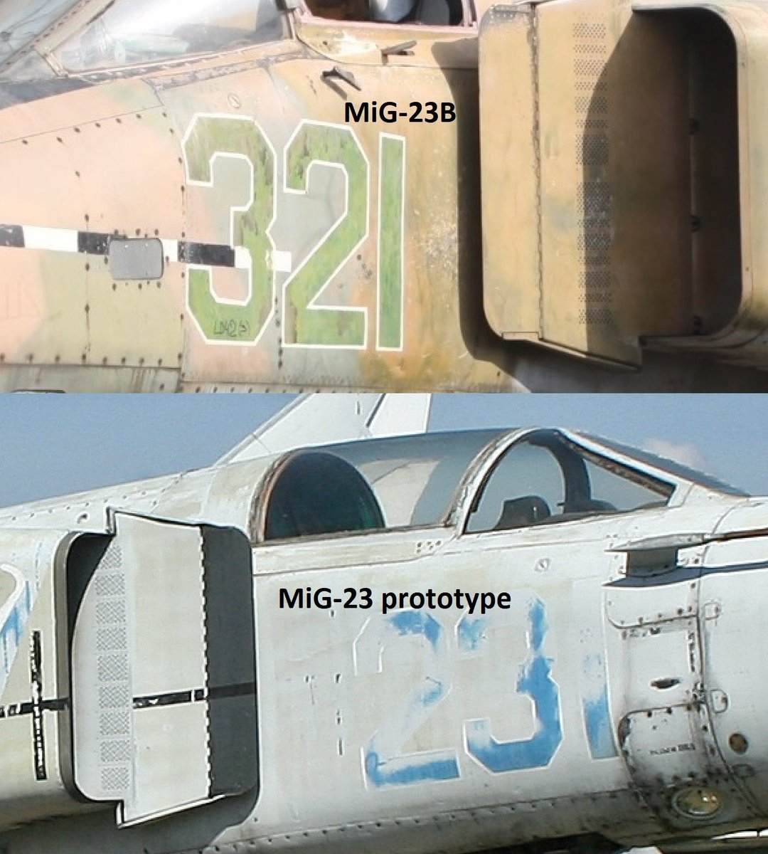
...started designing the MiG-23 intake by examining shot down F-4s wreckage, why are the early designs less like the F-4's? My first thought is that a copied design would diverge from the original, with each iteration, not converge. Maybe they hoped that the fewer bleed-holes...
...would be enough. I really don't know.
I'm beginning to see a pattern here. Judging from photos, the Su-15TM also has 3-oblique shock design intake ramps, like the MiG-23. But the second oblique is on the fixed portion of the ramp. F-106 for comparison.

It's very faint, and might be just my imagination. Here are some better views. Source: britmodeller.com/forums/index.p…
A few more words about the F-4 vs. MiG-23 intake design. The way the ramps are scheduled is also a bit different.
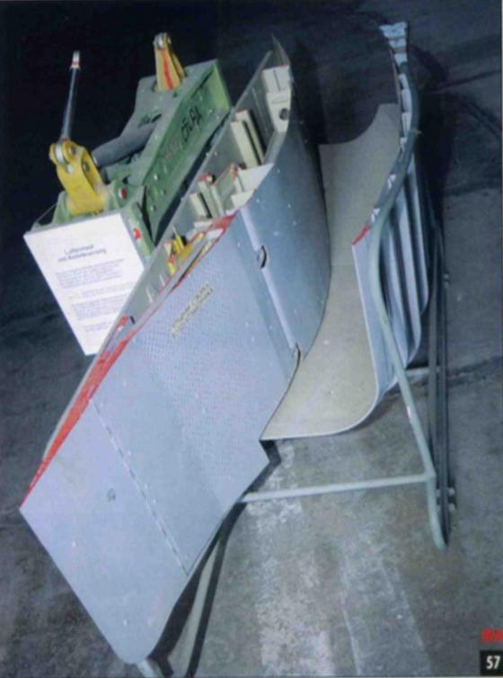
MiG-23MF variable intake ramp
MiG-23MF variable intake ramp
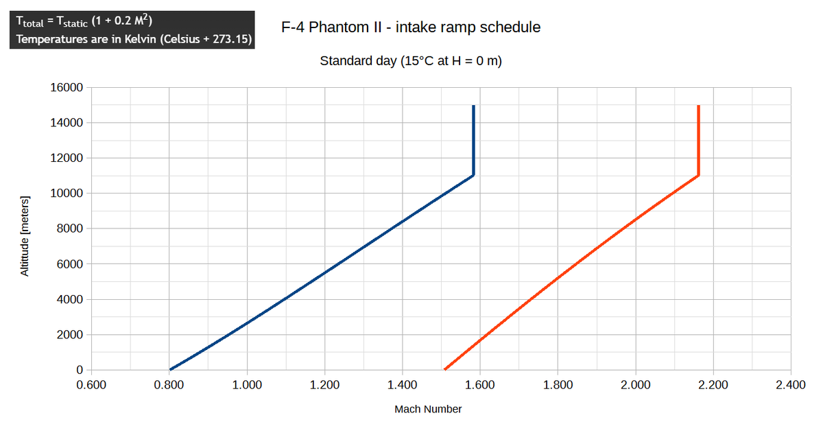
The F-4 ramp schedule is a function of total (stagnation) compressor inlet temperature (CIT). On a standard ICAO day (t = +15°C at H = 0 m), they begin to move at an outside air temperature (OAT) t = +52°C, corresponding to M ≈ 1.5 at H = 11000 m).
The values given in the F-4 flight manuals seem to be approximate, as a quick check with the stagnation temperature formula can show. For example, at 11000 m, t = -56.5 °C, means that total CIT = +52 °C is achieved at M ≈ 1.583. Full extension is achieved at CIT = +146 °C

Here is a chart that I calculated that shows the start & final Mach at which ramp movement begins & stops considering a standard ICAO atmosphere, CIT start = +52 °C, CIT final = +146 °C. At H = 11000 m, M start = 1.581, M final = 2.160.
The MiG-23UB witha UVD-23 ramp system, has a schedule based on compressor pressure ratio (so do the MiG-21PF to BIS).

The MiG-23ML with ARV-26A ramp system, has a schedule based on corrected RPM (the MiG-29 does too).

Schematic of the F-4's air intake & duct (air induction system).

Another one.

In the F-4's air induction system diagram you can also see how the air flow is regulated internally. A variable position ring moves back & forth to increase/decrease the amount of air that by-pases the J79 for cooling and the ejector nozzle to work properly.
A better understanding can be had from this A-5C Vigilante diagram from the flight manual. When slow or stationary, the cooling air flow can be supplemented by opening the auxiliary air doors.

The MiG-23's system is a bit different, but essentially the same, as can be seen in this page from the MiG-23ML 23-12B structural description manual
Instead of doors you have a fixed air scoop (3 on the figure) and a series of small poppet valves (8 on the figure) that...
Instead of doors you have a fixed air scoop (3 on the figure) and a series of small poppet valves (8 on the figure) that...
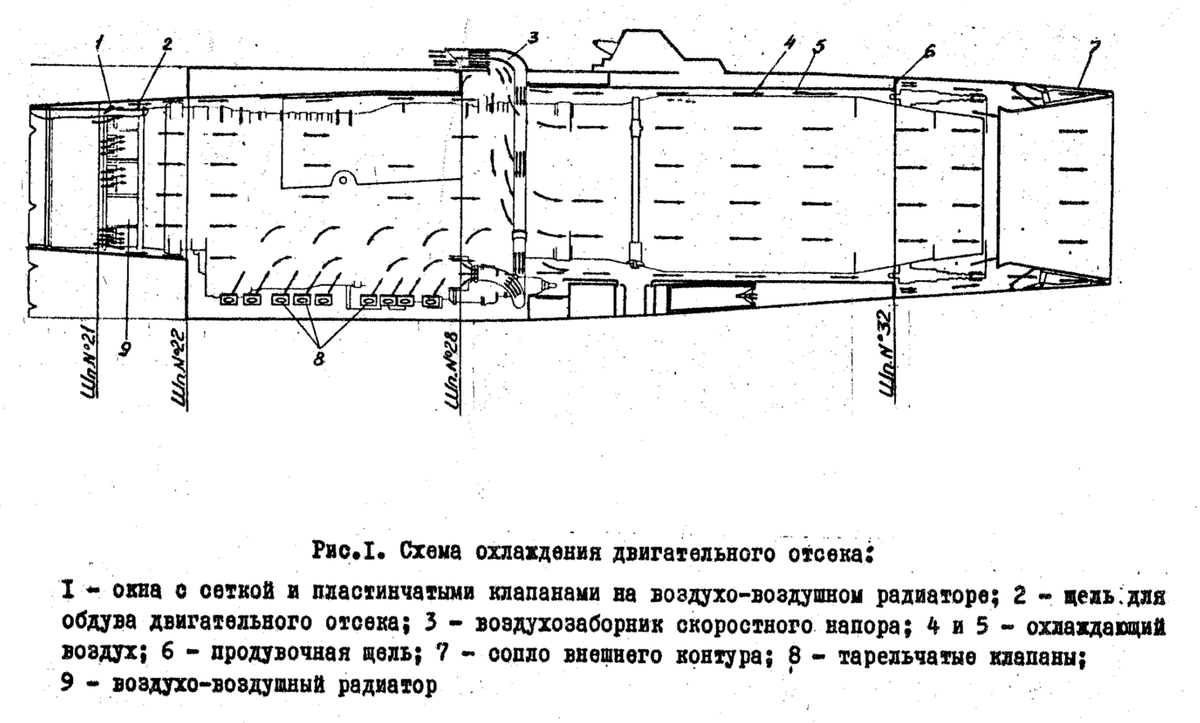
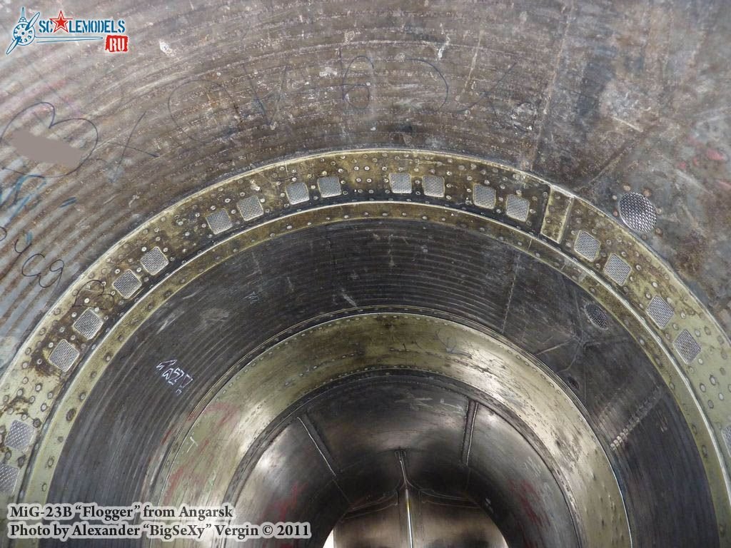
...open to allow more air when necessary. The main by-pass flow is provided by wire mesh windows with plate valves around the engine compressor intake (1 on the figure).
This system is also used on the MiG-21.
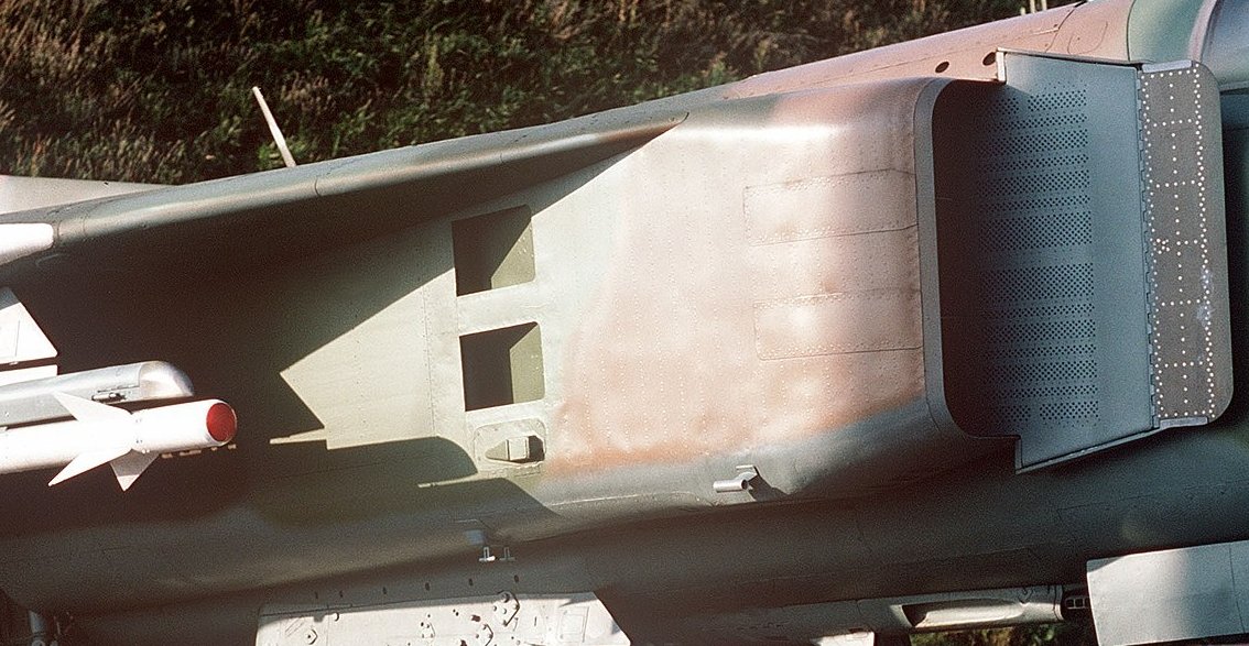
Here you can see the fixed air scoop on top of this MiG-23BN.
This system is also used on the MiG-21.
Here you can see the fixed air scoop on top of this MiG-23BN.

Here you can see the wire-mesh windows distributed circumferentially in the air channel of a MiG-23BN.
• • •
Missing some Tweet in this thread? You can try to
force a refresh