Ryan Hansen Space Profile picture
Feb 20, 2024 7 tweets 4 min read Read on X
Interesting parts are taking shape at #SpaceX's Masseys test site. As more work is completed on the new flame diverter, seemingly random parts start developing into recognizable assemblies. In this short thread, I'll present some ideas surrounding these new parts. As always, this is speculative and subject to change. /1Image
As always, I do my best to model in detail with accurate measurements from recreated camera shots. Here are my models with one of the images I used from @RGVaerialphotos's recent flyover. Consider becoming a flight supporter as things get more interesting at the Masseys site. /2 Image
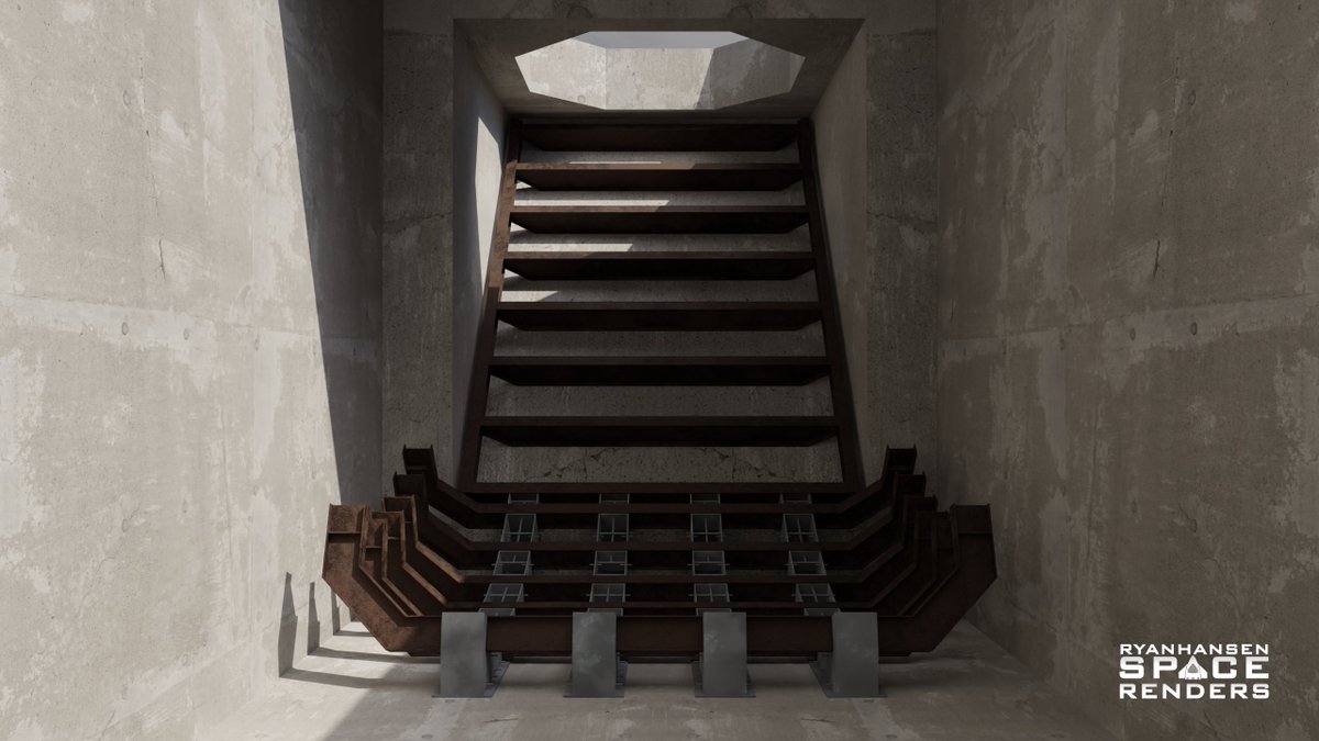
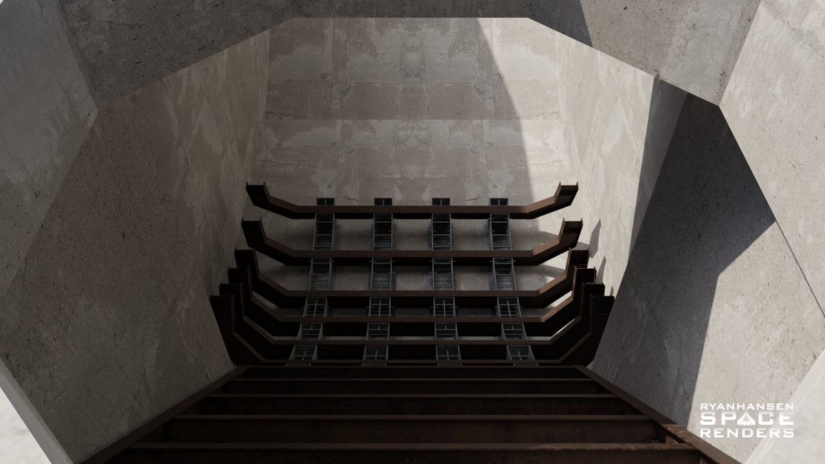
First up is the assumed "flame bucket" part of the diverter system. This will be built using 4 pedestals with 6 slots allowing the 6 "C" shaped beams to be attached to form the frame for a curved surface with walls. /3 Image
The pedestals appear to be hollow and have anchoring pegs inside and out suggesting that they will be embedded in concrete and filled with concrete once assembled. /4
Image
Image
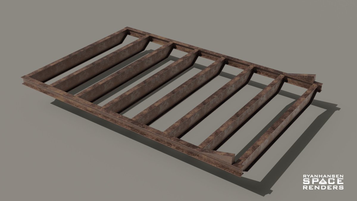
This truss platform has been around for weeks now. I initially thought it could be for a roof section but its width suggests that it will be narrower than the flame trench. Based on my understanding it only fits one place. More details on that next./5
Image
Image
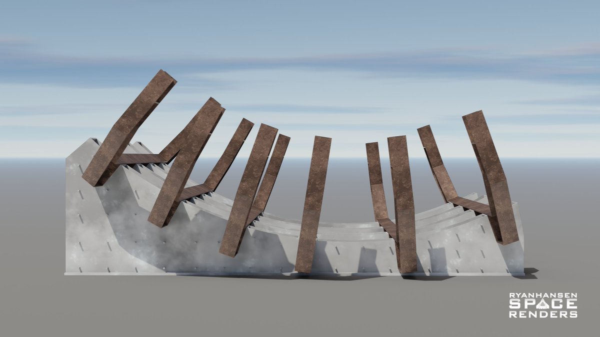
This is highly speculative, but given the recent foundation for what appears to be the business end of the flame trench, it appears that these assemblies could be related and form the primary diverter frame. Once installed they could look similar to this. 6/ Image
I will continue to update these models as things develop. There are still many unanswered questions and I would not be surprised if, by the next flyover, things look entirely different. Check back for updates in the near future. /7
Image
Image

• • •

Missing some Tweet in this thread? You can try to force a refresh
 

Keep Current with Ryan Hansen Space

Ryan Hansen Space Profile picture

Stay in touch and get notified when new unrolls are available from this author!

Read all threads

This Thread may be Removed Anytime!

PDF

Twitter may remove this content at anytime! Save it as PDF for later use!

Try unrolling a thread yourself!

how to unroll video
  1. Follow @ThreadReaderApp to mention us!

  2. From a Twitter thread mention us with a keyword "unroll"
@threadreaderapp unroll

Practice here first or read more on our help page!

More from @RyanHansenSpace

May 5
#SpaceX is preparing to move the massive new #Starship launch mount structure for #Starbase Pad B to the launch site for installation. In this post, I’ll give an overview of the design and use my 3D models to calculate the structure’s mass in its current configuration.

This new launch mount, nearly an entire redesign, is SpaceX’s best effort at correcting many of the issues discovered with the mount at Pad A after a handful of launches. The only similarity between this mount and the original launch mount for Pad A is that 20 arms will still be used to support the #SuperHeavy booster before liftoff. However, the arms and everything else making up the structure are entirely different.
This new launch mount has three main layers. The bottom layer is a truss section formed by four beam sections and four highly strengthened corner sections. Together, they create a square, with the beams distributing the weight of a fully loaded Starship vehicle into the corners and down onto the four pedestals on which the mount will sit at the launch site. The interior of these beams will likely be used for crew access and running pipework, which will provide water and other fluids for the mount’s functions.Image
The middle layer contains the launch mount's primary structure. This structure consists of 8 main sections, forming an icosagon in the center and a square exterior. These sections contain parallel walls with pivot points for hardware associated with each of the 20 support arms. At liftoff, the 20 support arms will retract into the space between these parallel walls. Large pistons mounted to the base of each pair of walls push and pull on the support arms to actuate them between positions.Image
Read 7 tweets
Jan 21
Here's a detailed thread that breaks down some of the information suggesting that Starbase Tower B will be used to catch the first Starship and not Tower A.
Let's start by looking at the catch points attached to #Starship S33 before Starship Flight 7. While I understand that these catch fittings were non-structural, their primary purpose was to analyze their thermal performance. You'd only get valid data if you used the hardware you intended to use later with structural versions. In this image from @StarshipGazer, we can see the catch fitting covered in tiles and the contact point hanging below the arm.
x.com/StarshipGazer/…
In various Discord chats and RGV Starbase Weekly episodes, I've repeatedly pointed out that this hardware was incompatible with the arms on Tower A. Specifically, the contact point. This slightly curved rectangular metal plate on the underside of the arm does not extend down far enough from the arm to create a gap large enough for the lip on the landing rail to not contact the underside of the arm. Using this hardware on Tower A would lead to the catch fitting getting damaged by the lip on the landing rail, resulting in tiles being crushed and the weight of the ship possibly damaging the lip on the landing rail during a catch attempt.Image
Read 14 tweets
May 5, 2024
The #Starship #SuperHeavy Booster Quick Disconnect (BQD) has been one of the most difficult Starship-related items to model due to its geometric complexity. The BQD operates primarily using only 2 pistons at the base of the structure to push or pull on the parallel frames which moves the BQD interface (and associated hardware and hoses) and operates the door through several linkages making this system as simple as possible from a controls standpoint. 1/5
Recently, the BQD received a new door. This new door features an additional protrusion allowing for additional space under the door. It was originally thought this could be for extra strength as the original door seemed to warp after a few launches. I had a different opinion and alluded to the purpose of this protrusion on @RGVaerialphotos Starbase Weekly, Ep.114. After reviewing many reference images taken by @StarshipGazer I have determined what this new protrusion and hardware is for and modeled it the best I can given the limited views we have of the hardware. 2/5Image
This new hardware adds a mechanism to the BQD door with several black discs that move to seal the GSE ports on the BQD interface when retracted back into the hood. This should help mitigate Foreign Object Debris (FOD) from getting into the pipes during liftoff and when the BQD is not in use. It is impossible to see the backside of this mechanism so the placement of the pistons is an educated guess. 3/5
Read 5 tweets
Mar 9, 2024
Shortly before I posted my first detailed thread about my #SuperHeavy #B9 propellant simulation results, #SpaceX rolled B10 to the launch site, and some new weld marks were observed in the lower LOX tank. Like others, I also speculated this may indicate new slosh baffles. /1 Image
It appears SpaceX determined the existing baffles within the LOX tank aren’t enough to mitigate slosh at staging. Using the weld marks, I devised a few designs and tested them with the same conditions as the previous thread to see how each design would change the liquid behavior. /2
Before looking at any new simulations, let's look at the original side cutaway. I will be using this angle and animation throughout this thread to make comparisons. Also, keep in mind my disclaimer in the previous thread about these results and their theoretical accuracy. /3
Read 20 tweets
Feb 14, 2024
It's finally time to unveil my #SuperHeavy #B9 propellant simulation results! In this thread, I will
include some animations with data and provide some brief details about the process. I may make another thread explaining this process in more detail at a later date if desired. /1 Image
I started this project the day after #Starship IFT-2 with some basic tests. It took nearly a month to go from a conceptual idea to a workflow that seemed like it could work and produce fairly accurate results with the limited data that onlookers have access to. /2
Simply put, the plan was to recreate the flight path and match the tracking camera angles. Then animate my models to match the motion of B9 and then use that animation data to calculate the 3-axis acceleration of B9 for every frame. Then I could use that acceleration data to drive forces within a fluid simulation. /3
Read 21 tweets
Jul 7, 2023
Since my last thread, #SpaceX has made a lot of progress with the upgrades beneath the #Starship OLM. In this thread, I will give an updated look at the transpirationally cooled steel plates and explain how they will all come together as well as some additional speculation. 1/n
If you haven’t seen my previous thread I HIGHLY recommend checking it out first. It has a lot of details that I either won’t mention here or will expand on or correct and it might be confusing without any context. 2/n
Shortly after the first of the year, SpaceX began building different sub-sections. It was clear there would be several different shapes consisting of rectangles, trapezoids, and recently revealed, hexagons. Several different configurations of some shapes were also used. 3/n
Read 28 tweets

Did Thread Reader help you today?

Support us! We are indie developers!


This site is made by just two indie developers on a laptop doing marketing, support and development! Read more about the story.

Become a Premium Member ($3/month or $30/year) and get exclusive features!

Become Premium

Don't want to be a Premium member but still want to support us?

Make a small donation by buying us coffee ($5) or help with server cost ($10)

Donate via Paypal

Or Donate anonymously using crypto!

Ethereum

0xfe58350B80634f60Fa6Dc149a72b4DFbc17D341E copy

Bitcoin

3ATGMxNzCUFzxpMCHL5sWSt4DVtS8UqXpi copy

Thank you for your support!

Follow Us!

:(