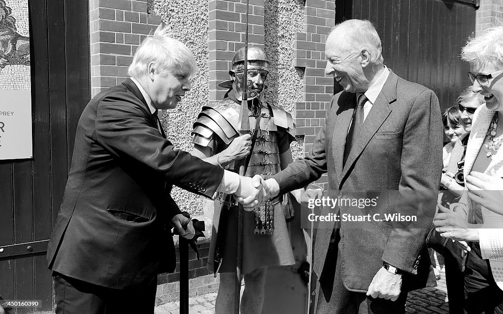
Boris Johnson SLAMS Keir Starmer's digital ID plan for immigration - 'Br... via @YouTube
I’m just bemused by this.
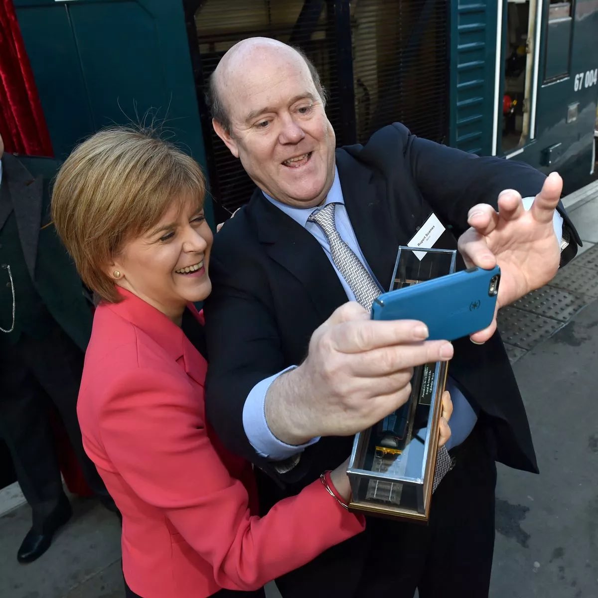
Yes, former UK Prime Minister Boris Johnson received the COVID-19 vaccine. He had his first dose of the Oxford-AstraZeneca vaccine in March 2021 at St. Thomas' Hospital in London, the same hospital where he had been treated for COVID-19 the previous year.
Johnson's vaccination timeline included additional doses:
•Second dose: He received his second dose in June 2021.
•Booster dose: He received a booster shot in December 2021.
During the pandemic, he was a vocal supporter of the UK's vaccine rollout program and encouraged others to get vaccinated.
Johnson's vaccination timeline included additional doses:
•Second dose: He received his second dose in June 2021.
•Booster dose: He received a booster shot in December 2021.
During the pandemic, he was a vocal supporter of the UK's vaccine rollout program and encouraged others to get vaccinated.
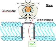
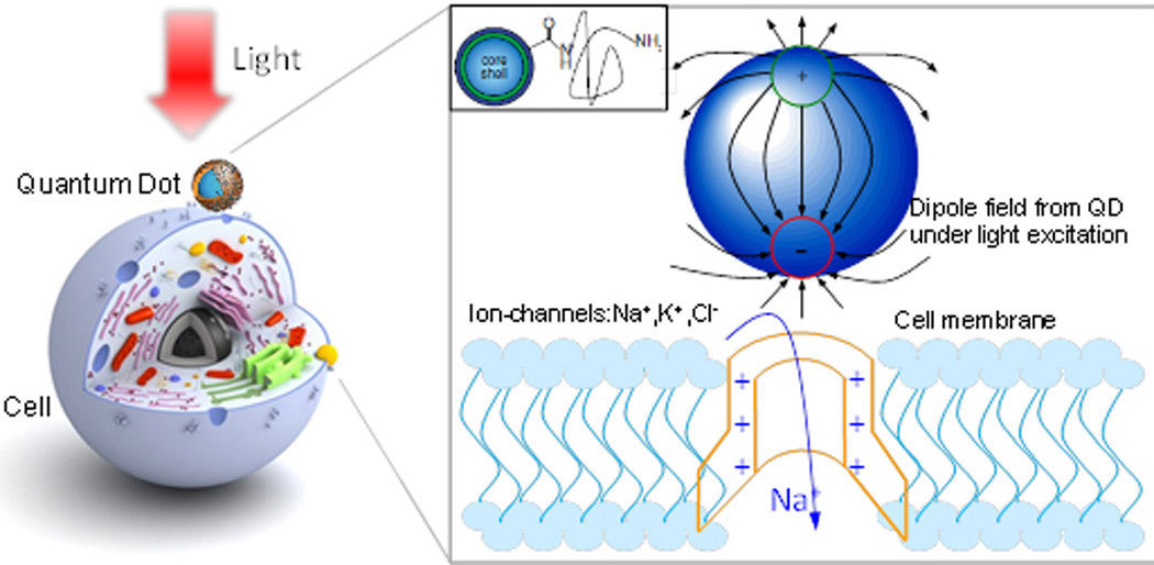
How ironic is this Ai has machine learned to digitally identify scrupulous wee lying bastards pushing a quantum mind control agenda using toxic nanoparticles that cause blood brain barrier dysfunction …and they knew this all along but still ran the risk?regardless.
That can only mean one thing that Boris Johnson is culpable.
Note: Serco's connection to St. Thomas' Hospital during the COVID-19 pandemic is linked to controversies surrounding the NHS test-and-trace program and a prior contract for pathology services. While the Guy's and St Thomas' NHS Foundation Trust was at the forefront of treating COVID-19 patients, Serco was not directly involved in the hospital's clinical services during the pandemic.
🤔
•Serco was previously in a joint venture, Viapath, with Guy's and St Thomas' and King's College Hospitals to provide pathology services.
•This partnership ended in 2020 after the trusts selected a different provider for a new contract, forcing them to buy out Serco's share
•Serco was previously in a joint venture, Viapath, with Guy's and St Thomas' and King's College Hospitals to provide pathology services.
•This partnership ended in 2020 after the trusts selected a different provider for a new contract, forcing them to buy out Serco's share
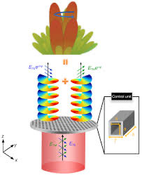
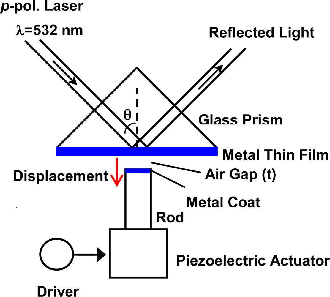
An LCD screen can be used to display computer-generated holograms for holographic optical tweezers (HOT), a system that uses computer-controlled laser traps to manipulate microscopic particles in three dimensions. In this setup, the LCD acts as a spatial light modulator (SLM)that encodes and projects the desired hologram, which reshapes the laser light to create multiple, independently movable traps in real-time. This technique is used in fields like microfluidics and biomedical research for tasks like sorting particles or manipulating cells.

Schematic of a liquid crystal-based Spatial Light Modulator. Liquid crystals are birefringent, so applying a voltage to the cell changes the effective refractive index seen by the incident wave, and thus the phase retardation of the reflected wave


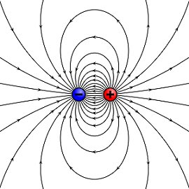
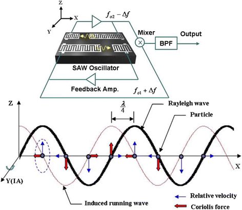
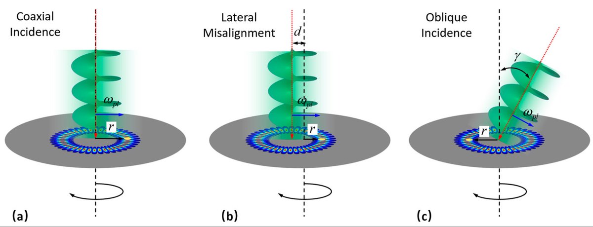
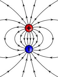
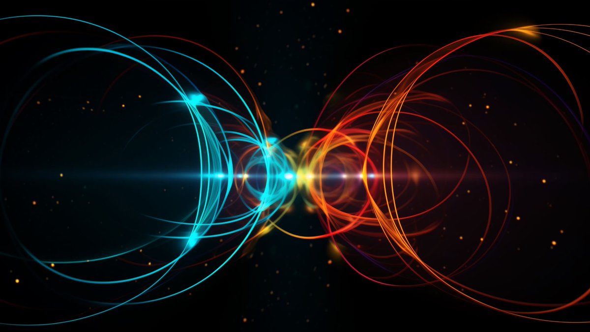
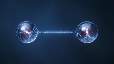
The image illustrates a standing wave or a concept related to the Sagnac effect.
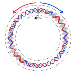
A standing wave is formed by the superposition of two or more traveling waves moving in opposite directions. In this diagram, the red and blue wavy lines represent two waves traveling around a circular path in opposite directions. As the waves interfere with each other, they create a pattern of nodes (points of zero displacement) and antinodes (points of maximum displacement) that appear to be "standing still".
A standing wave is formed by the superposition of two or more traveling waves moving in opposite directions. In this diagram, the red and blue wavy lines represent two waves traveling around a circular path in opposite directions. As the waves interfere with each other, they create a pattern of nodes (points of zero displacement) and antinodes (points of maximum displacement) that appear to be "standing still".
The concept of waves traveling in opposite directions on a circular path is also central to the Sagnac effect. In this phenomenon, two beams of light travel in opposite directions around a closed loop, such as in a ring interferometer. If the loop is rotating, the time it takes for each beam to complete the circuit will be different, leading to a phase shift that can be measured. This effect is used in technologies like fiber-optic gyroscopes to detect rotation.

The appearance of the wheels and their work was like unto the colour of a beryl: and they four had one likeness: and their appearance and their work was as it were a wheel in the middle of a wheel.


Got it

I get this.
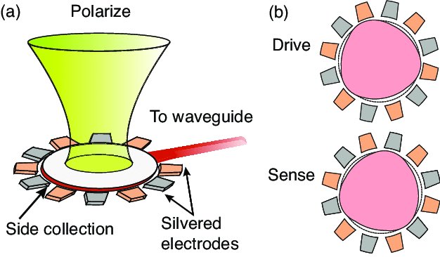
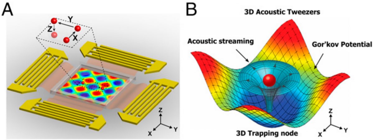
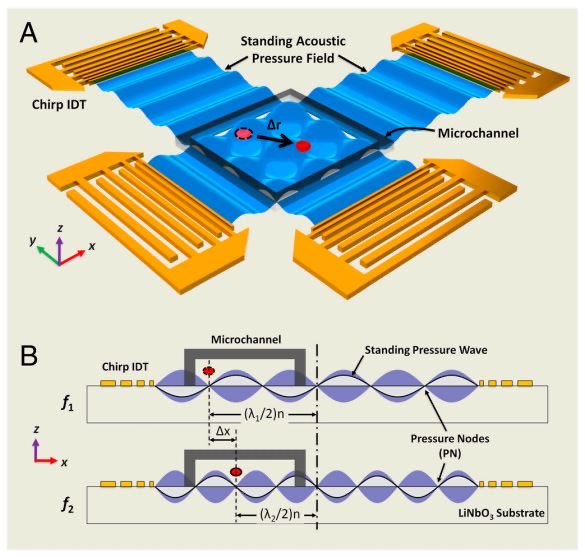
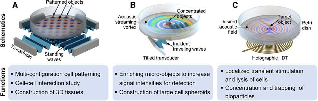
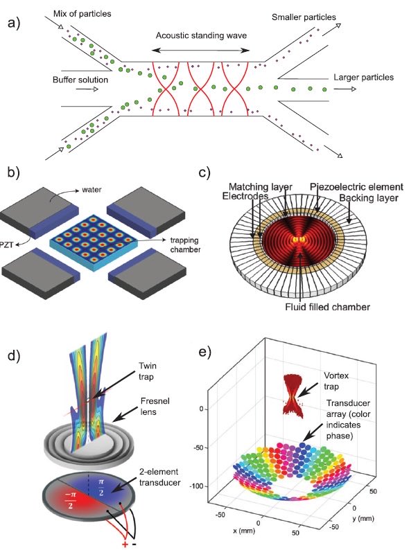
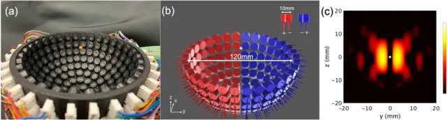
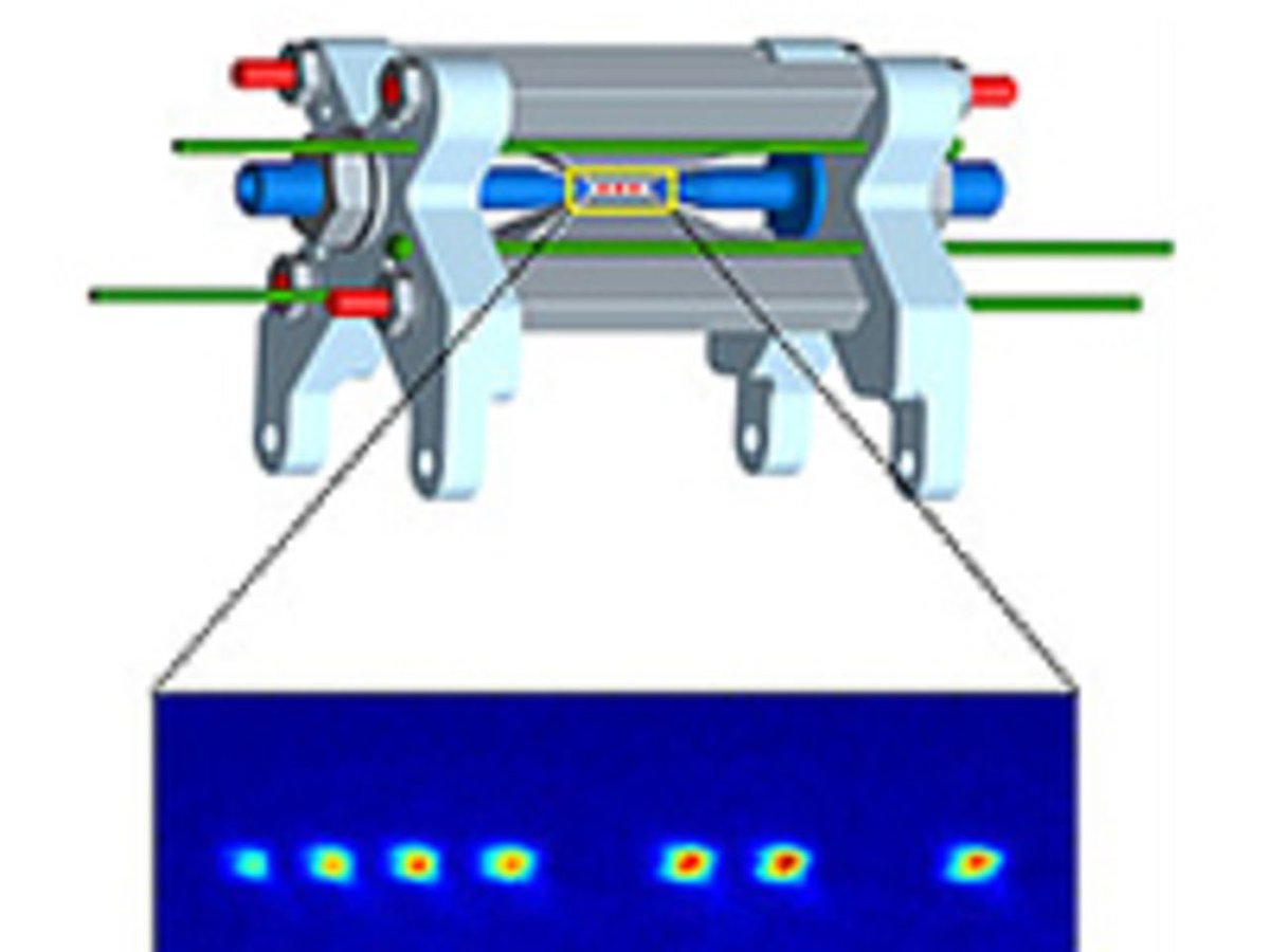
Acoustic tweezers
Acoustic tweezers


Hold this thought…
HoldinG on for you


Catch and release
They are all going down.
Catching up with them
Caught red handed
Touching
Positive 1+
Let’s play stupid.
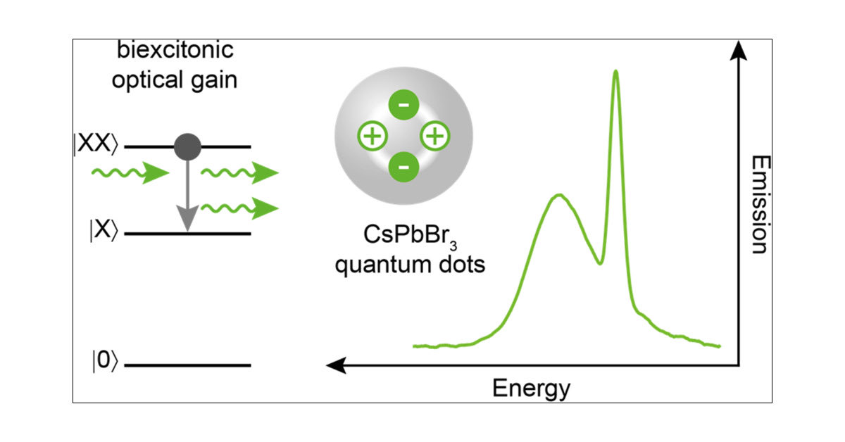
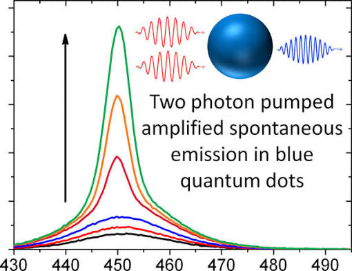
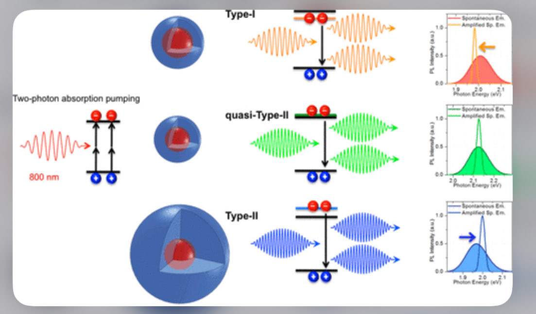
Attractive versus Repulsive Excitonic Interactions of Colloidal Quantum Dots Control Blue- to Red-Shifting (and Non-shifting) Amplified Spontaneous Emission


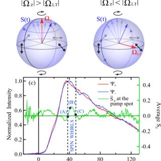


(a) Incoherent superposition of two spatially uniform fully polarized beams with normalized intensities 0.9 and 0.1. (b) Point inside a Poincaré sphere representing a light beam described by the Stokes vector S obtained as the incoherent superposition of two beams described by the Stokes vectors Se and Se⊥ on the surface of the sphere. Equivalent superposition of (c) two fully polarized vector beams and (d) scalar first-order Gaussian spatial modes. Figure (b) can be regarded as the (a) standard polarization PS, (c) HOPS or (d) OAMPS. The polarization ellipses corresponding to partially polarized light in (a) and (c) describe the polarized part of the state, and they have been rescaled with the DoP.
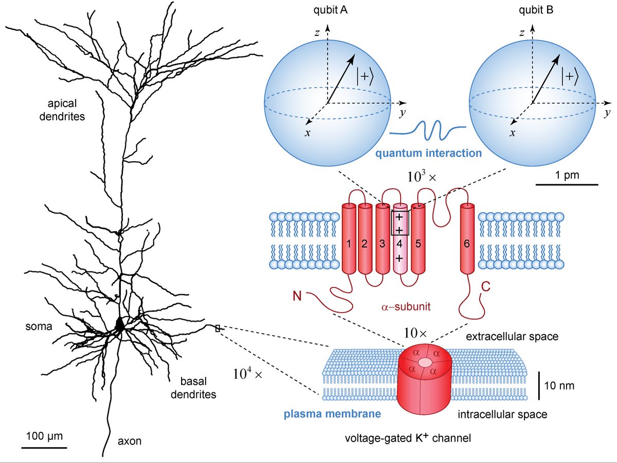
The image shows a Bloch sphere, which is a geometric representation of the state space of a single qubit (quantum bit).
•A qubit is the basic unit of information in quantum computing, analogous to a bit in classical computing.
•A qubit is the basic unit of information in quantum computing, analogous to a bit in classical computing.

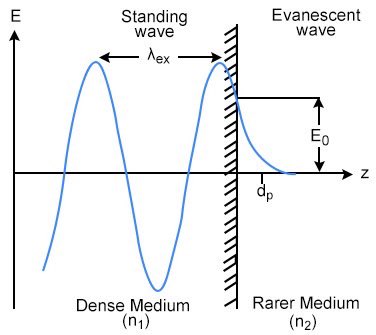
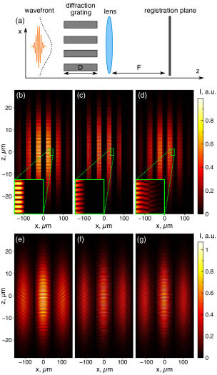
Diffraction can be understood in terms of evanescent fields, which are non-propagating electromagnetic fields that exist at the interface of two media with different refractive indices, as seen in phenomena like total internal reflection. By creating periodic structures or using subwavelength gratings, these evanescent fields can be manipulated to create spin-dependent diffraction, and their interactions can lead to effects like transmission enhancement or suppression in various applications, such as near-field microscopy and integrated optics

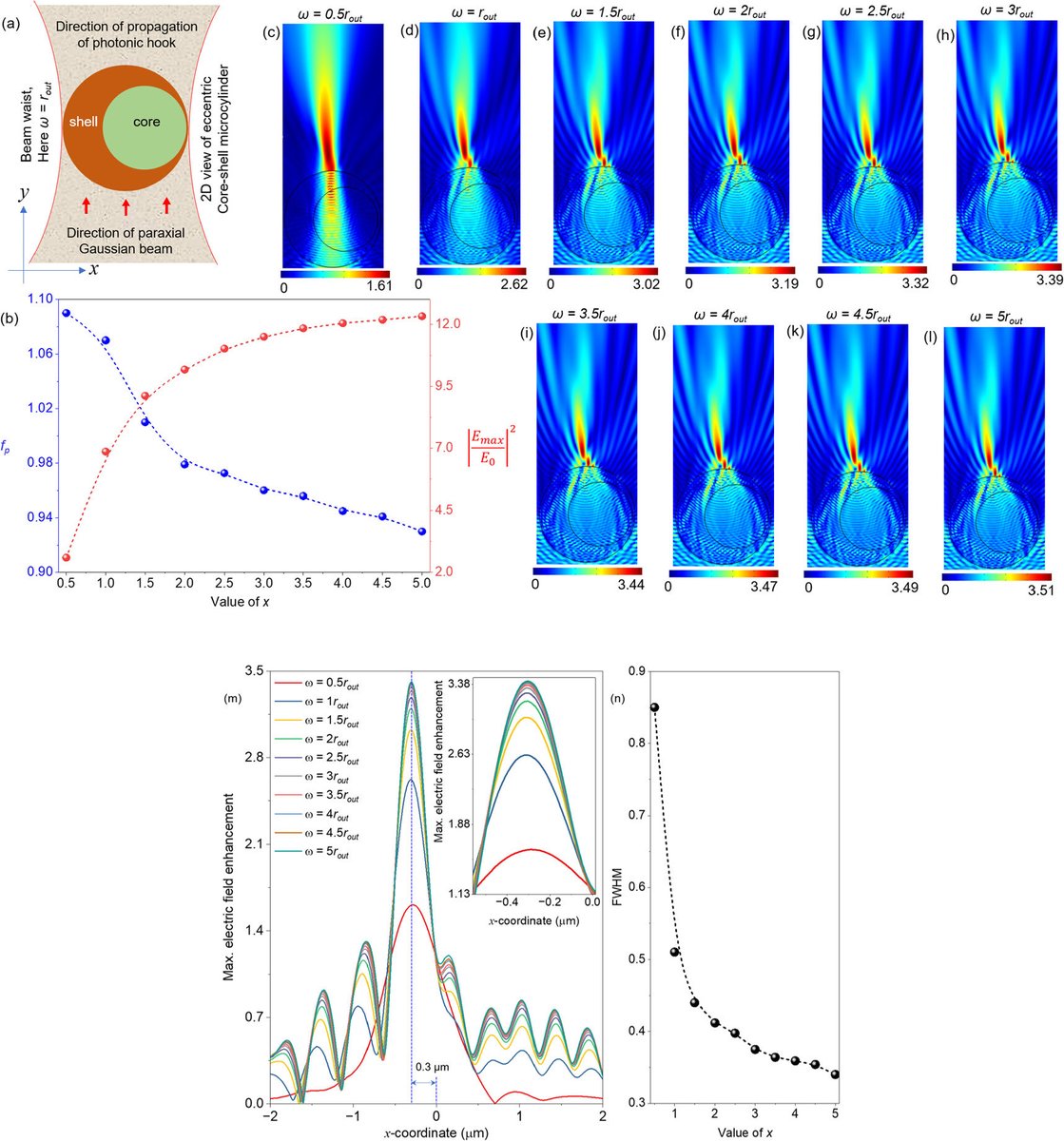
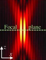
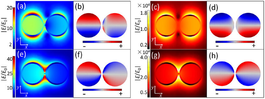
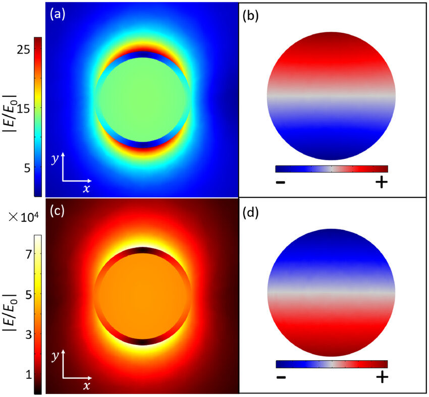
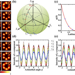
The image shows a series of diagrams and graphs related to the generation of a photonic hook from an eccentric core-shell microcylinder. A photonic hook is a type of curved, high-intensity light beam with a subwavelength beam waist. This phenomenon is a result of symmetry breaking in the microcylinder structure, in contrast to a photonic nanojet which is formed by symmetrical microstructures.
The image illustrates the following aspects of this phenomenon:
•Schematic Diagram: Figure (a) shows a 2D view of the eccentric core-shell microcylinder and the direction of the paraxial Gaussian beam used to illuminate it.
•Electric Field Distribution: Panels (c) through (l) show the maximum electric field distribution of the photonic hook for different values of beam waist, 
•ω
0
𝜔
0
. The number under each panel indicates the maximum electric field enhancement value, 
•E
m
a
x
2
E
0
2
𝐸
2
𝑚
𝑎
𝑥
𝐸
2
0
.
•Beam Waist and Field Enhancement: Graph (b) shows the relationship between the eccentricity parameter, x, and the maximum electric field enhancement and focal length, 
•f
p
𝑓
𝑝
.
•Electric Field Profile: Graph (m) displays the maximum electric field enhancement profile along the x-coordinate at the focal plane for different beam waist values.
•FWHM and Eccentricity: Graph (n) shows the variation of the Full Width at Half Maximum (FWHM) as a function of the eccentricity parameter, x.
This study uses numerical simulations based on the finite-difference time-domain (FDTD) method to investigate the characteristics of these curved light fields. The properties of the photonic hook, such as its curvature and intensity, can be tuned by adjusting parameters like the eccentricity of the core-shell microcylinder, the refractive indices of the core and shell, and the beam waist of the incident light. The study suggests potential applications for photonic hooks in fields such as super-resolution imaging and micromachining.
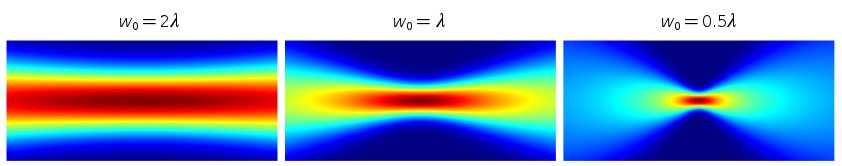
the direction of the paraxial Gaussian beam used to illuminate it…
A paraxial Gaussian beam is a laser beam whose transverse intensity profile follows a Gaussian function and whose propagation is described by the paraxial approximation. It represents the lowest-order and most common mode of output from many lasers, known as the TEM00 mode
Interval.
Transmission electron microscopy (TEM) is a microscopy technique in which a beam of electrons is transmitted through a specimen to form an image. The specimen is most often an ultrathin section less than 100 nm thick or a suspension on a grid. An image is formed from the interaction of the electrons with the sample as the beam is transmitted through the specimen. The image is then magnified and focused onto an imaging device, such as a fluorescent screen, a layer of photographic film, or a detector such as a scintillatorattached to a charge-coupled device or a direct electron detector.
A TEM image of a cluster of poliovirus
A TEM image of a cluster of poliovirus
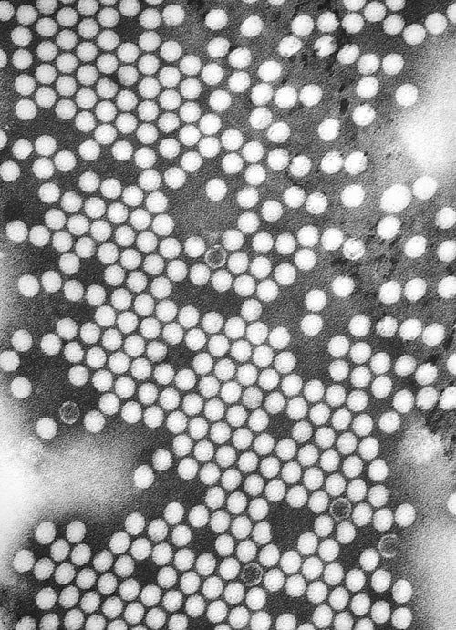
Transmission electron microscopes are capable of imaging at a significantly higher resolution than light microscopes, owing to the smaller de Broglie wavelength of electrons
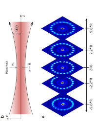
The image represents a standing wave on a circular path, a concept used in physics to visualize wave-particle duality and the quantization of energy.
In quantum mechanics, this type of model is often used to illustrate the de Broglie hypothesis, which suggests that particles like electrons can also behave as waves. For an electron's wave to form a stable orbit around a nucleus, it must be a standing wave, meaning a whole number of wavelengths must fit exactly into the circumference of the orbit. If the wave did not fit perfectly, it would undergo destructive interference and cancel itself out, resulting in an unstable state.
This model provides a physical explanation for the discrete, or quantized, energy levels of electrons in the Bohr model of the atom. The different standing wave patterns, such as the ones shown in the image, correspond to different energy levels and angular momentum values for the particle.
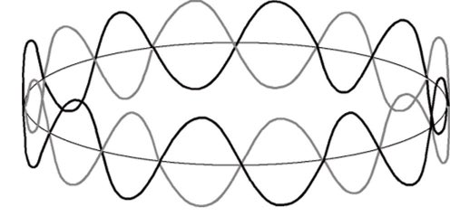
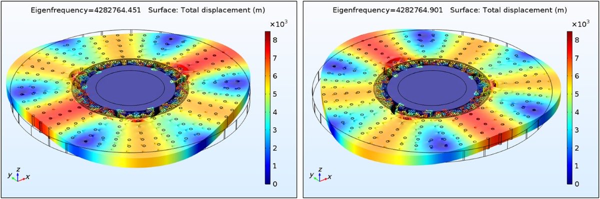
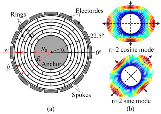
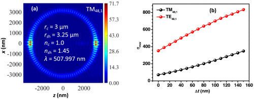
Standing waves in the ring resonator can be mathematically described by changing the position term, kx, in the linear standing wave expression ( ψ = A cos κx + B sin κx) × cos ωt ) to mφ where m is a positive integer and indicates the number of wavelengths that fit into the circumference for the particular mode in question. Having m = 0 is not common but is allowed in some wave systems.
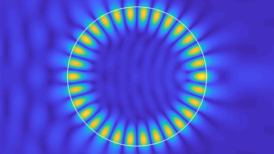
A standing wave in a Whispering Gallery Mode (WGM) resonator is formed when light waves interfere with themselves inside a WGM resonator, creating a fixed pattern of nodes and antinodes. This phenomenon is crucial for various applications, as it concentrates light in a small volume, which enhances light-matter interactions for sensing, nonlinear optics, and cavity optomechanics. Unlike a simple traveling wave, a standing wave has points of zero and maximum amplitude, making it ideal for applications like high-precision sensing or generating new light frequencies.
•Standing waves only occur at specific, resonant frequencies where the wave fits perfectly around the cavity. At these frequencies, constructive interference creates the standing wave pattern.
•Standing vs. traveling waves:In contrast, a traveling wave moves continuously around the resonator. A standing wave is a superposition of two traveling waves moving in opposite directions.
•Standing vs. traveling waves:In contrast, a traveling wave moves continuously around the resonator. A standing wave is a superposition of two traveling waves moving in opposite directions.
•Standing waves can be used to create a standing wave pattern, further concentrating the optical field in a smaller volume, a property known as a "deeply sub-diffractive mode volume".
•High-sensitivity sensing: The predictable and stable standing wave pattern makes WGMs excellent for highly sensitive sensors. Changes in the surrounding environment can be detected by how they perturb this standing wave.
•Nonlinear optics: The high intensity of the circulating light in a standing wave can be used to efficiently generate new frequencies (second-harmonic generation) at low input power
ISRAELITE
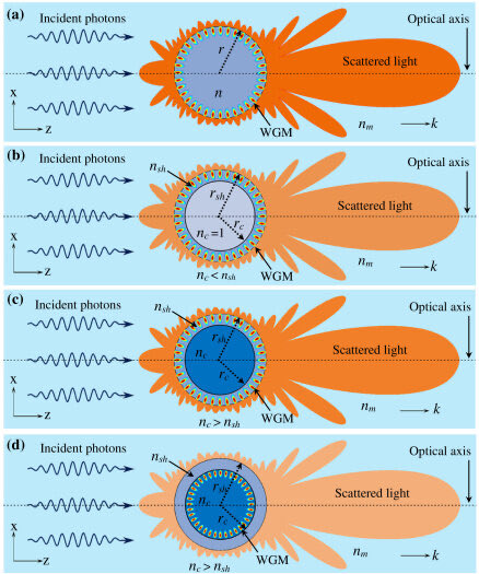

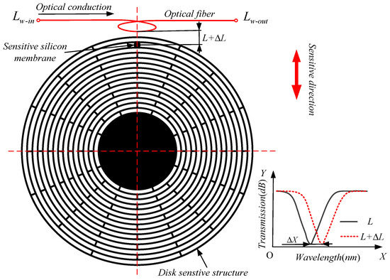
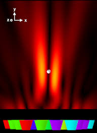
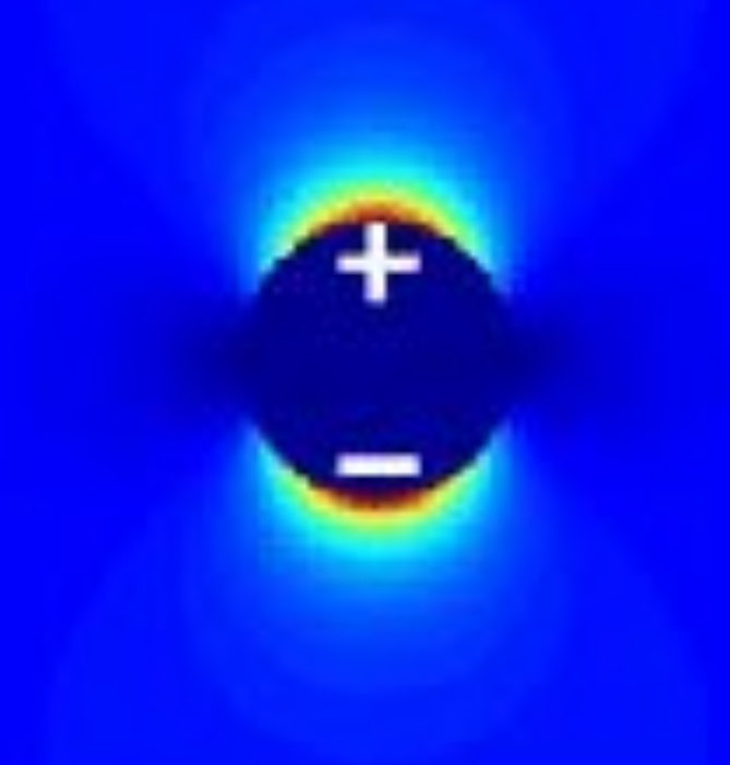
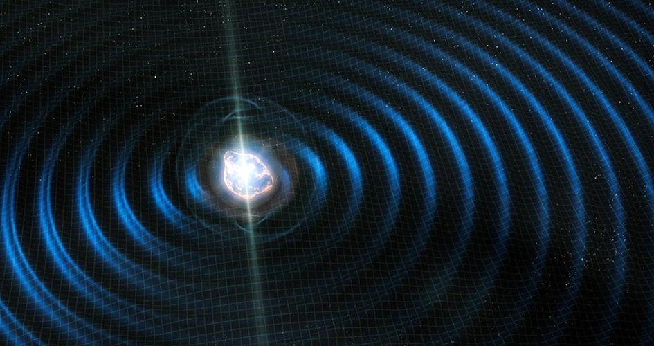
The image is a visualization of a whispering gallery mode (WGM), which is a type of optical resonance that occurs in a circular or spherical cavity
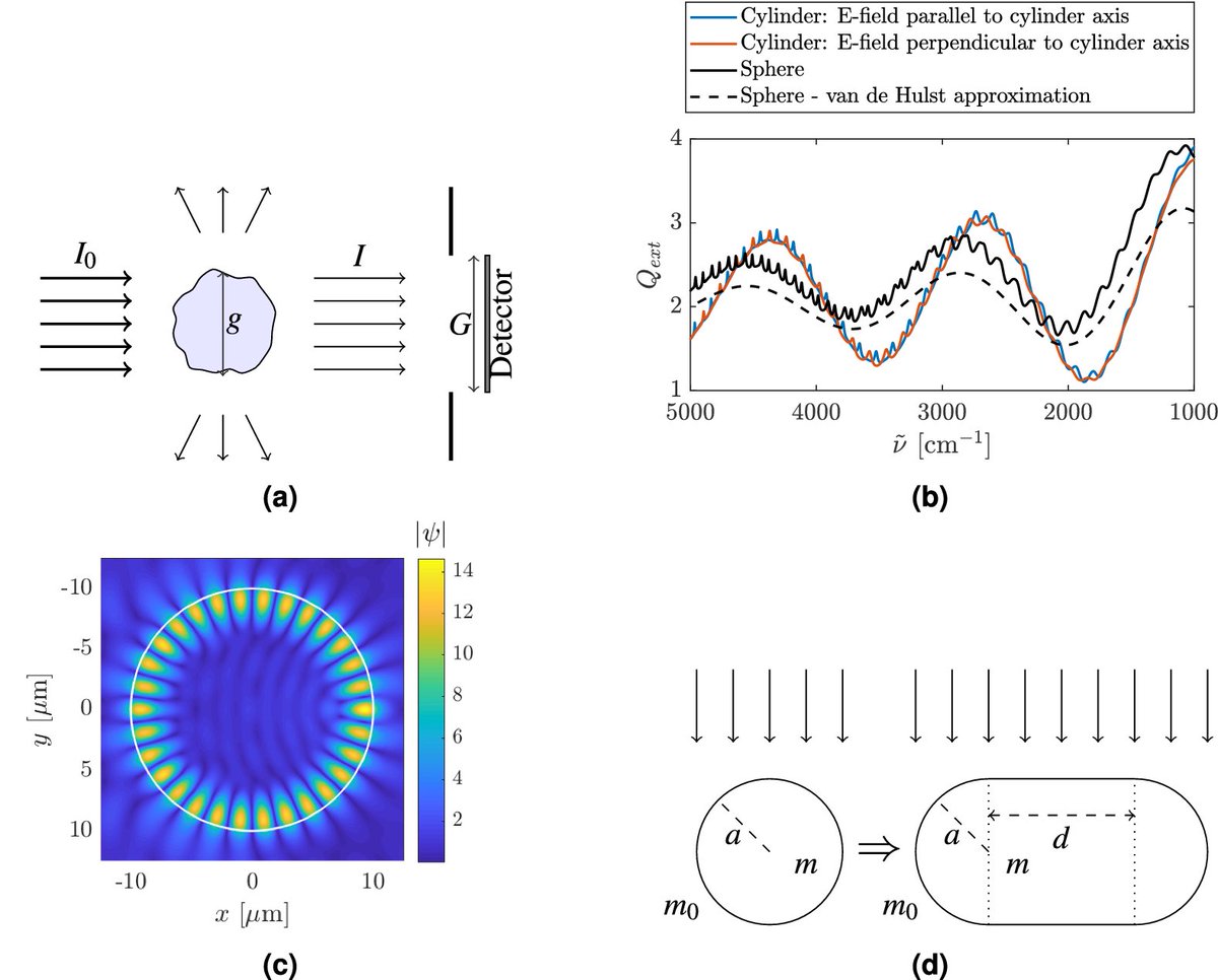
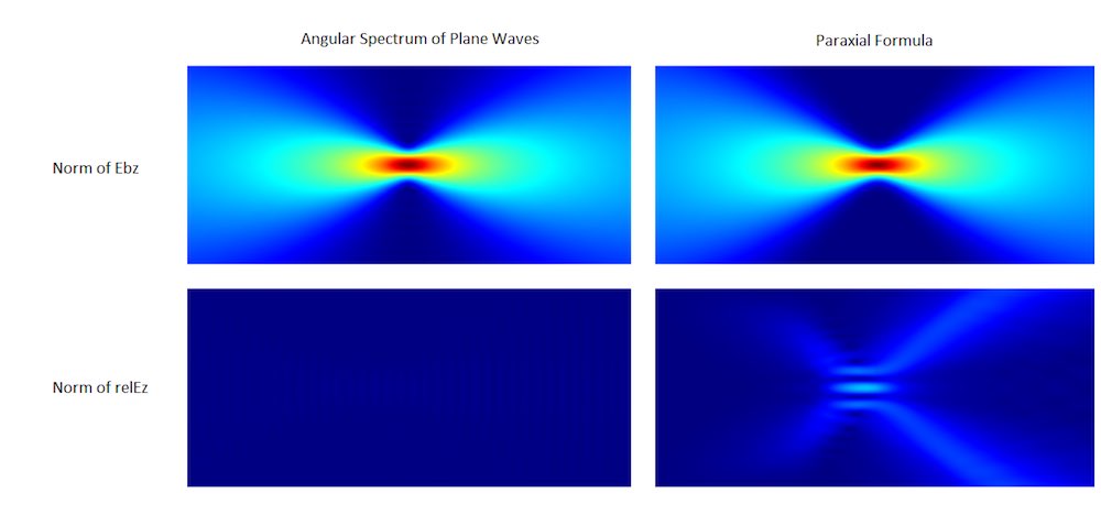
The image is a simulation of a photonic jet, which is a highly localized, high-intensity electromagnetic field that can be generated when a plane wave is scattered by a dielectric sphere or cylinder

• • •
Missing some Tweet in this thread? You can try to
force a refresh