The economics of AI has been a big question mark in many investors' minds - What does the value chain look like? How do you model out the ROIC of AI? What would the ROIC look like?
We built up an end-to-end economics stack to answer this question - how we go from a chip’s silicon cost, through full system integration, all the way down to the dollar cost per million inference tokens.(1/4)🧵
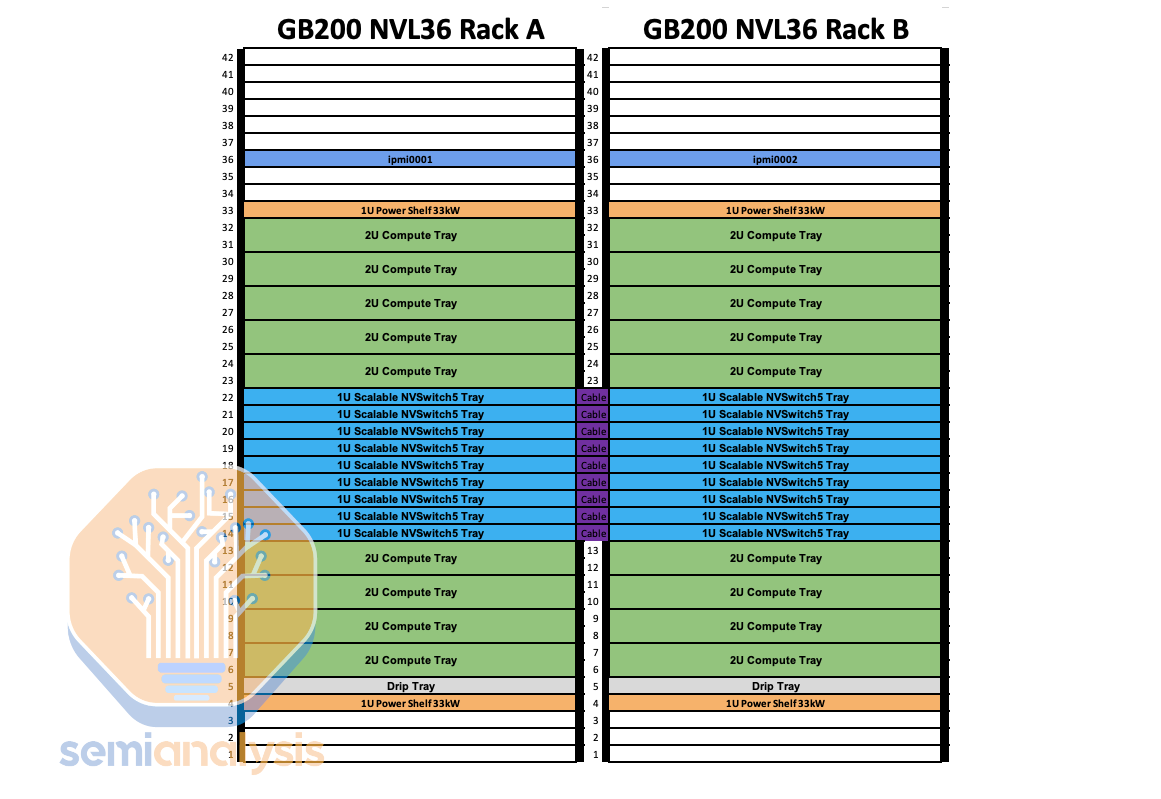
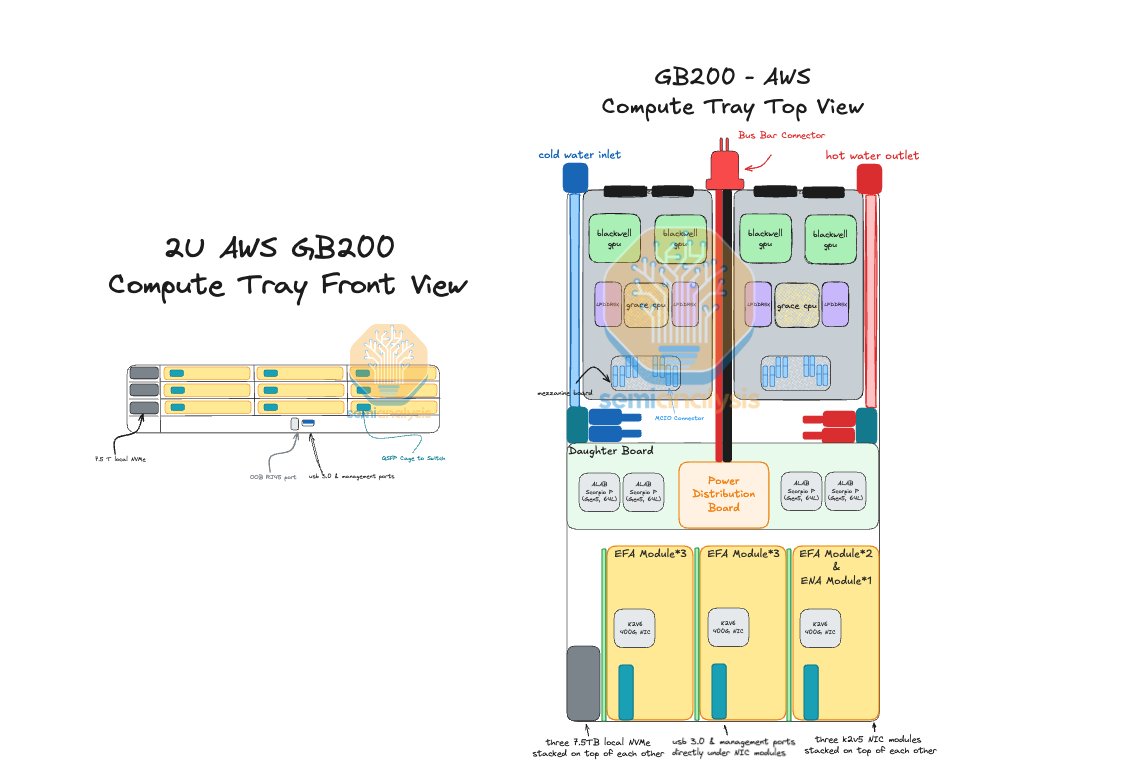
At the top of the stack, our accelerator analysis starts with the semiconductor bill of materials (transistors, packaging, HBM, and yield assumptions) to determine GPU provider content. From there, our BoM and ODM modeling breaks down every component inside the server. The network topology model then maps how these servers interconnect.(2/4)
When you roll this all up, illustratively for H200s, that gives us a capital cost of roughly $1.06 per GPU-hour, to which we add electricity and colocation costs for a complete TCO of $1.41 per GPU-hour. That’s the economic foundation. The cost to own and operate the hardware. A neocloud might rent that same GPU for roughly $2 per hour, leaving a modest gross margin. But until now, that’s where most analysis stopped at TCO/hr.(3/4)
The missing piece was InferenceMAX™, which gives us rigorous, real-world throughput data. Using DeepSeek R1 FP8 runs on H200s, we can now translate cost per GPU-hour into cost per million tokens, about $0.53 per million tokens.
Finally, once we couple that compute cost with real application metrics (average tokens per user, token price, and active user counts) we can close the loop from silicon economics all the way to application-layer profitability. In this example, we land at roughly 34% gross margin at the app level. This framework lets us, for the first time, connect token demand forecasts to megawatt requirements. As models evolve and inference efficiency improves, these relationships will keep shifting - but this stack gives us a repeatable way to translate demand into hardware, power, and ultimately, answer the question on economics.(4/4)
• • •
Missing some Tweet in this thread? You can try to
force a refresh
Qualcomm and MediaTek are in a race to reduce their dependency on the mature smartphone market. Both are still managing to beat unit growth in smartphones. But that won't last long. Investors are looking for their progress in non-smartphones. Qualcomm's non-smartphone chip business hit a $10B+ annual run-rate, contrasting with MediaTek's $8B+. (1/7) 🧵
Both have increased their investments to capture more revenue in consumer, networking, industrial and computing markets. Non-smartphones account for 30% of Qualcomm's semiconductor revenue and 48% of MediaTek's. Qualcomm has a target of $22B non-smartphone chip revenue by FY29 at a 5-year CAGR of 21%. Qualcomm built a strong moat in autos but made mixed progress in IoT (a collection of end markets including PC, consumer, networking and infrastructure). (2/7)
After sitting on the sidelines for a long time, both Qualcomm and MediaTek have now firmed up their AI datacenter chip plans. MediaTek appears to have hit gold with its AI ASIC business, claiming $1B revenue in '26, multiple billions in '27 and up to $5B-$7.5B in '28 and beyond (10-15% share of $50B TAM), growing faster than its flagship smartphone chip business, which will slow down from CY26. (3/7)
AI workloads are characterized by elephant flows when all of the GPUs in a cluster exchange data through collective communication operations to synchronize data for distributed workloads. These flows can often lead to congestion and load balancing issues. (1/6)🧵
To solve this problem, Meta turned to the use of Disaggregated Scheduled Fabrics (DSFs). Being “Scheduled” means that a credit-based system is used to control flows and prevent congestion – before a node can send packets across the network, it must first send a credit request towards the receiving node to make sure that the receiving end has enough buffer to receive the packet. These packets also travel over a fabric that cellifies the packets, breaking it into smaller cells and spreading it across multiple routes in the fabric. (2/6)
Arista’s 7800R series of “Big Boy” Chassis switches provide such a scheduled fabric, as well as what is effectively a very high radix switch, but the downside is that all the ports are all in one physical location. (3/6)
CMP (Chemical-Mechanical Polishing) is a type of planarization process that uses a slurry to thin or polish the wafer surface to achieve a smooth, mirror-like finish. As early as 1980, CMP was developed by IBM specifically as a technique for dielectric planarization.
Aside from wafer edge grinding, etching, dielectric deposition, metal deposition and other thin films, CMP is used commonly throughout the process.
There are several applications of CMP including copper interconnects, removal of USG (undoped silicate glass) films formed during the STI (shallow trench isolation) and polysilicon removal on DRAM surfaces. (1/8)🧵
Interestingly, the use of this technique for wafer surface planarization was initially unexpected. The reason is straightforward, in traditional semiconductor processing, direct contact with the wafer surface is strictly prohibited, as it can cause defects and particle contamination. In turn, it leads to reduced manufacturing efficiency and lower yield. However, it has now been proven that this technique not only enables surface planarization but also reduces defect density and improves yield. (2/8)
CMP plays a crucial role and has the following 4 advantages:
⚆ It can help meet with the higher resolution demands of advanced process nodes. An uneven surface causes light scattering and nonuniform reflection, which degrades resolution.
⚆ It also helps eliminate the high resistance of metal interconnects caused by sidewall thinning, a problem that arises from the poor step coverage of PVD processes. As the metal film becomes thinner along the sidewalls, current density increases, raising resistance and accelerating electromigration.
⚆ It can also reduce exposure requirements and prevent CD loss from overexposure at the same time. This issue is from photoresist thickness nonuniformity caused by the dielectric step structure.
⚆ It allows more uniform surface deposition while reducing residue and minimizing the time required for over-etching, thereby preventing undercutting and substrate damage caused by prolonged over-etching.
Because CMP involves the use of slurry and downward pressure, particle contamination and delamination can occur. Therefore, it must be followed by a cleaning process to effectively reduce defect density. (3/8)
Etching is a process used to remove material from the wafer surface to meet the design requirements of an integrated circuit (IC).
There are two types of etching: one is patterning etching, which removes material in specified areas, such as transferring patterns from a photoresist or hard mask layer onto the substrate film. Another type is blanket etching, which removes the entire surface film to meet process requirements, for example, backside wafer etching. (1/11) 🧵
Etching also can be categorized into two types based on characteristics: wet etching and dry etching. Wet etching is typically performed at room temperature, requiring no additional vacuum equipment, RF systems, or gas delivery setup. The process is relatively easy to control, making the equipment significantly cheaper than that used for dry etching. Below, we will introduce each in detail. (2/11)
However, the chemical reaction itself has no directional preference—making wet etching inherently isotropic.
Isotropic etching means that material is removed not only vertically but also laterally, leading to an undercut effect. This undercut prevents accurate pattern transfer to the wafer and can cause line collapse in sub-3-micron processes, leading to their gradual replacement by dry (plasma) etching. (3/11)
AWS believes that their custom K2v5/6 NIC with their in house EFA protocol has better perf than NVIDIA ConnectX-7/8 NICs but due to how increasingly how tightly integrated NVIDIA racks are, it becomes increasingly difficult for hyperscalers to use their own NICs. This is what led to AWS GB300 NVL72 to disaggregate their NICs from the compute tray into an NIC only sidecar called "JBOK". Below we breakdown the decisions and constraints that led to this design. 👇1\N 🧵
For GB200, AWS only supported GB200 NVL36x2 and NVL36 which allowed up to 72 GPUs per NVLink domain while allowing each rack to be 66kW power & 2U compute trays by connecting 2 NVL36 with NVLink ACC cables. As many GCP & AWS customers have noticed, NVIDIA's driver & physical engineering support for NVL36x2 has been lackluster and way more bugs than their standalone NVL72 design. Although AWS markets their NVL36x2 as "NVL72", it is not topologically equivalent to an actual NVL72. 2/N🧵
The reason AWS GB200 wasn't able to do acutal NVL72 and had to do NVL36x2 & NVL36 was due to their need to fill 9 200GbE K2V5 NICs (8 EFA backend + 1 ENA/EBS frontend) per compute tray and that requires having an 2U compute tray. Only NVL36x2 & NVL36 supports 2U compute tray. NVL72 compute tray only supports 1U compute tray. 3/N 🧵
China’s State Council on October 9 approved Order No. 61 of 2025, announcing export controls on certain overseas rare-earth items. This marks the fourth round of rare-earth export restriction efforts; the previous round was on April 8.
(1/8)🧵
China’s new rare earth export controls focus on two key points:
⚆ Products containing Samarium (Sm), Dysprosium (Dy), or Gadolinium (Gd) originating from China that account for 0.1% or more of the item’s value must obtain a dual-use export license.
⚆ Rare earth materials are not permitted for military use.
⚆ Exports related to the R&D or production of sub-14 nm logic chips, 256-layer-plus memory chips, semiconductor equipment, or AI with potential military use, which will now require case-by-case approval.
(2/8)
When people hear the term “rare earth,” they often assuming these elements are hard to find. However, rare earth elements are not scarce on Earth. The real challenge is that they are usually mixed with other minerals. This makes extraction and refining difficult and expensive. Therefore, rare earth metals are not “rare”—they are simply “hard to obtain.”
(3/8)