
1/ Here's the thread for me hand-soldering a lead-free Glasgow board. This will be🤞the first PCB that I fully assemble. Likely to have major problems due to my n00b soldering skills which should make it very interesting to test and troubleshoot 😀
Soldering the iCE40 FPGA took two tries. First chip floated off the pads and deposited its solder balls at random. Cleaned up with braid and Metcal blade tip. Second chip looks good to me. (Have to separately reball the first chip for reuse.)
USB controller was a shit-show. I've never soldered a heat-dissipating ground pad using lead-free solder before and I really struggled to make solder flow both with the iron and hot air. I'm not convinced I succeeded. And that's with a preheater cranked up underneath the PCB!
I am an idiot: after soldering the USB controller kind-of okay-ish I then proceeded to remove it and resolder it with about ten times too much heat. I wanted to see it floating and jiggling over the pad to indicate full reflow but couldn't make it happen. Too little solder maybe?
I've used most of my Glasgow parts for soldering exercises. This means that to assemble a complete board now I need to scavenge some parts from my practice boards. Here's how it looks to scavenge a part, dilute out the old leaded solder, and prepare for a final cleanup. Fun!
Here's a little montage of random soldering on my Glasgow today. I have so much new soldering gear that I'm still working out which tool to use for what, which tip to choose, what angles that tip works at, etc. Making messes, cleaning them up. Fun!
I made some teeny tiny solder bridges yesterday. That's good news because correcting solder bridges with a microscope and good flux is one of the most relaxing activities that I know.
Here's a close-up. The "big" soldering iron tip is only 1mm wide!
Here's a close-up. The "big" soldering iron tip is only 1mm wide!
Had to scavenge a few more parts from a practice board today. Switched to the 0.5x barlow lens to fit both boards into the microscope field of view at once (from 0.7x.)
Fun to try "reverse drag soldering" using braid to turn giant bulbous bridges into neat-looking joints :)
Fun to try "reverse drag soldering" using braid to turn giant bulbous bridges into neat-looking joints :)
Here's me n00bing a relatively big part.
Skipped the added flux initially making the solder pasty; foolishly worked on the same side that was holding the part tacked in place; tried to make solder magically disappear by heating it with a conical tip before reaching for braid.
Skipped the added flux initially making the solder pasty; foolishly worked on the same side that was holding the part tacked in place; tried to make solder magically disappear by heating it with a conical tip before reaching for braid.
(Hey is that part on backwards? I need to check the orientation! I remember not being sure how to interpret the design and silkscreen compared with the package but I was too caught up in the moment to stop and think.)
Dumping a clump of 0402 MLCCs into a pool of gooey flux and then soldering them individually one terminal at a time.
Maybe would have been better to tin the first pads ahead of time, if only to mark where the parts go without having to glance over at KiCad all the time.
Maybe would have been better to tin the first pads ahead of time, if only to mark where the parts go without having to glance over at KiCad all the time.
I did some 0402s with hot tweezers. Here it's hard going at the start but then gets really easy. I suspect the fine tips had oxidized making heat transfer lousy but that the flux eventually burned that away. Or maybe I just didn't tin them evenly enough.
Just testing the new Quick TR1100 hot air pencil by straightening out some small parts on my Glasgow. Cool! I'm now able to rework individual small parts e.g. 0402 using hot air. Just reflowing them to let surface tension straighten them out a little here for fun and OCD.
I didn't RTFM on the TR1100 so one feature caught me by surprise. You can set a time limit on heat after which it beeps a warning and switches to cool-down mode. I wasn't ready for the sudden switch from gentle hot air to blasting cool air at max flow! Had to replace R10 :-)
Hey! Soldering away to complete my first Glasgow board still after a couple of weeks' distractions. Some obscure caps/resistors arrived from Mouser, other parts scavenged from a donor board (previous aborted effort using leaded solder.) Good fun!
I've also rigged a "lazy susan" turntable underneath my PCB preheater so that I can rotate the board keeping the same region in the microscope field of view (one handed and without having to touch stuff that's hot.) I know it's a boring demo but potentially a major convenience!
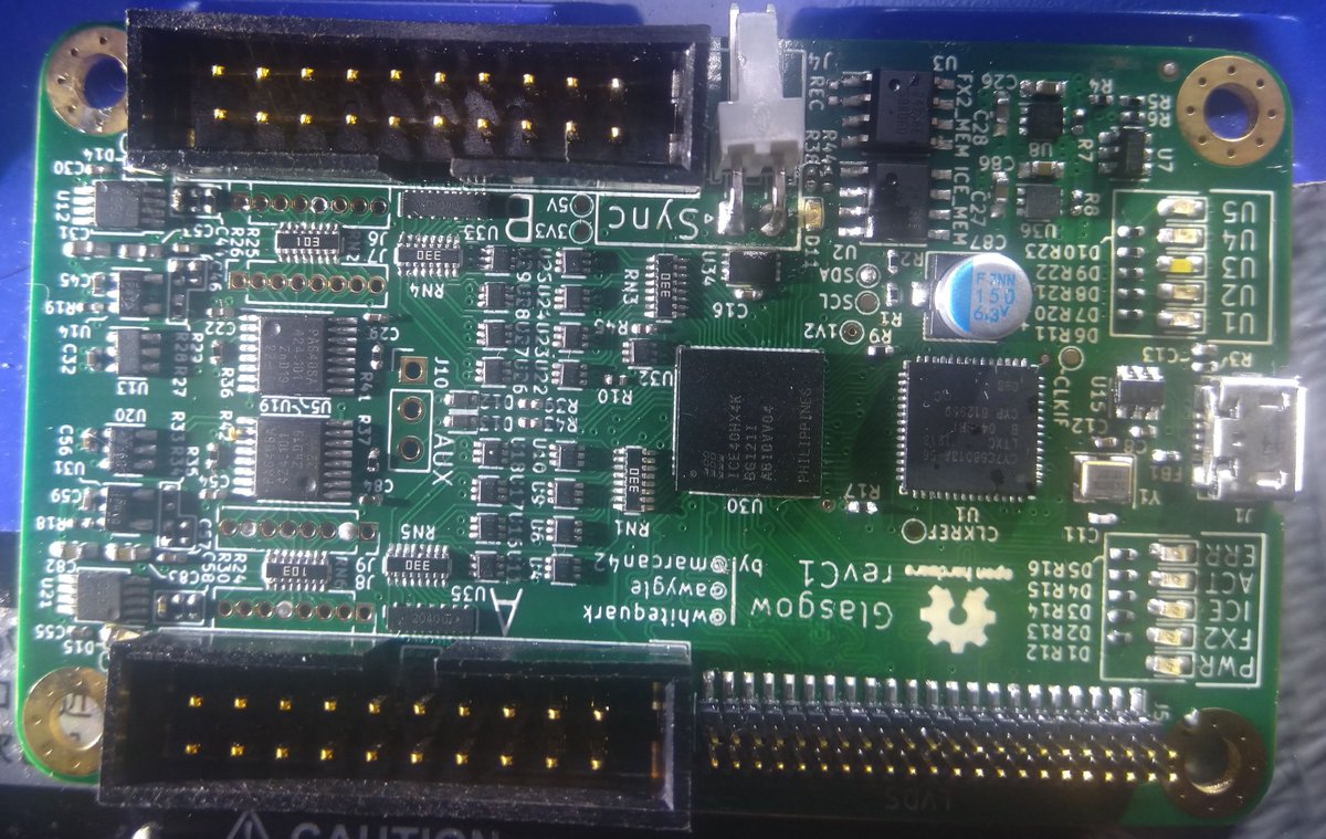
Hey I finally completed my first PCB assembly!!! Just soldered on the last parts.
I bet there are LOTS of mistakes. Have to think about proper inspection now: checking for missing parts, orientation of chips and diodes, bad solder joints... Or just plug it in and stand well back?
I bet there are LOTS of mistakes. Have to think about proper inspection now: checking for missing parts, orientation of chips and diodes, bad solder joints... Or just plug it in and stand well back?
First clumsy attempt at using the Eakins autofocus camera for inspection. I've no idea if I'm using the right lens etc. Sure is unforgiving to inspect "that looks basically okay" 0402 parts from oblique angles, yikes!
Walk of shame! Unflattering close-up showing many misoriented parts and some especially bad solder joints towards the end :-)
Looks like an afternoon of rework! Woohoo!
Looks like an afternoon of rework! Woohoo!
I had to reorient the majority of the six-legged transceivers, but it was done in a dash with the Quick TR-1100 micro air station and lazy susan to rotate PCB (and preheater.)
I did carelessly damage a big plastic connector in the process though so now I'll need to replace that!
I did carelessly damage a big plastic connector in the process though so now I'll need to replace that!
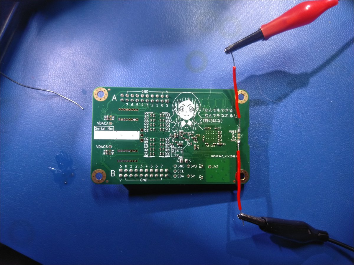
Amazing! Known problems are reworked (including U12, thanks @MarcelWiget 👍) and it's time to do multimeter tests and try supplying 5V to these test points with limited current from the bench supply.
Maybe an ultrasonic bath first to make sure no fresh flux gel is conducting...
Maybe an ultrasonic bath first to make sure no fresh flux gel is conducting...
Anticlimax... Hooked it up but it didn't draw any current... Now starts the real trouble shooting process for the first time...
So for today the status is that #glasgow have helped me to see that the 5V current is not propagating terribly far through the board. Tomorrow I'll do another inspection checking for missing parts, bad orientation, and reflowing any suspicious solder joints.
Let there be light! Some LEDs coming on now :) with patient tutoring from #glasgow and a lot of rework and bodge wiring to bring the power rails up one by one and fix misplaced parts.
Currently 1V2 for FPGA not stable and likely a BGA soldering problem.
Currently 1V2 for FPGA not stable and likely a BGA soldering problem.
Replaced the FPGA that was suspected to be badly soldered. Tricky 😬. I accidentally removed a lot of soldermask while cleaning up the pads which makes resoldering much less forgiving. Then used less flux, less air flow, lots of heat to try and avoid spreading solder around. 🤞
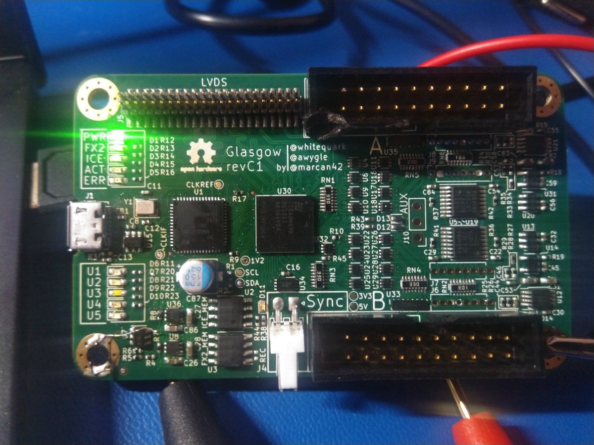
Getting close! My Glasgow now comes up on USB and gets programmed with gateware applets :-)
Selftest is reporting shorted pins though. Hope I can correct them! If it's under the BGA I'll probably need to repair the soldermask there and that could be hard...
Thanks #glasgow!
Selftest is reporting shorted pins though. Hope I can correct them! If it's under the BGA I'll probably need to repair the soldermask there and that could be hard...
Thanks #glasgow!
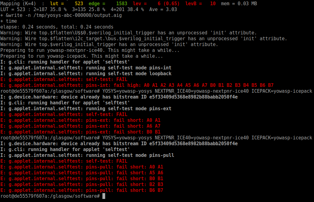
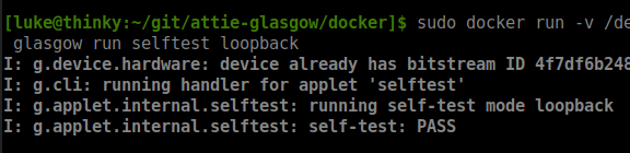
Close enough!!!
My Glasgow board passes the most basic selftest. I know (thanks #glasgow!) that there's a pair of pins short at I/O connector B but I'll worry about such minor issues later when I actually have a board to USE this Glasgow on.
So I have assembled a PCB now :)
My Glasgow board passes the most basic selftest. I know (thanks #glasgow!) that there's a pair of pins short at I/O connector B but I'll worry about such minor issues later when I actually have a board to USE this Glasgow on.
So I have assembled a PCB now :)
Screenshot of very exciting basic selftest...
• • •
Missing some Tweet in this thread? You can try to
force a refresh


