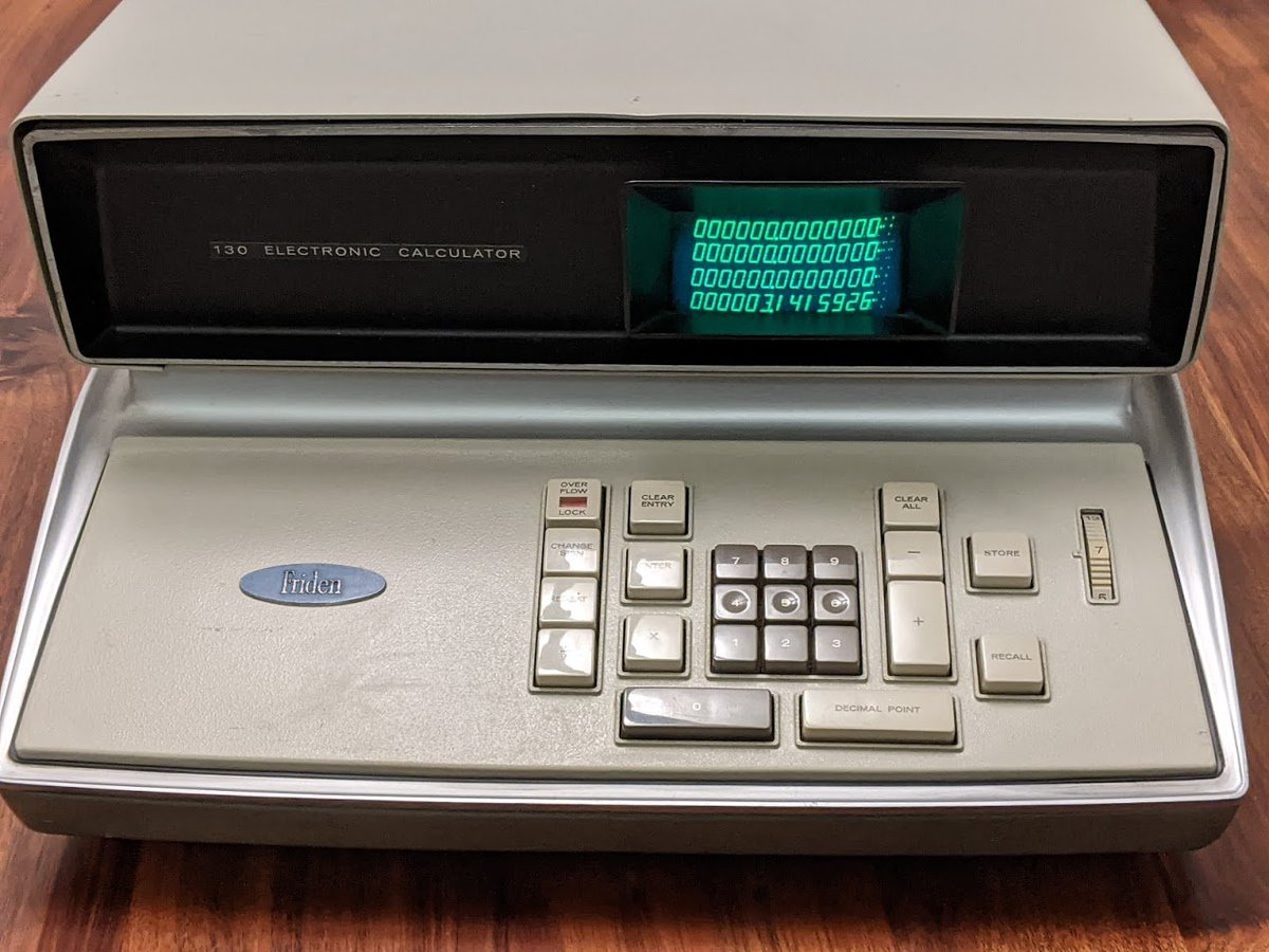
this is one of the world's first electronic calculators, the Friden EC-130, which came out in 1964! it's a really fascinating machine, so let's look at it in more detail. 🧵 
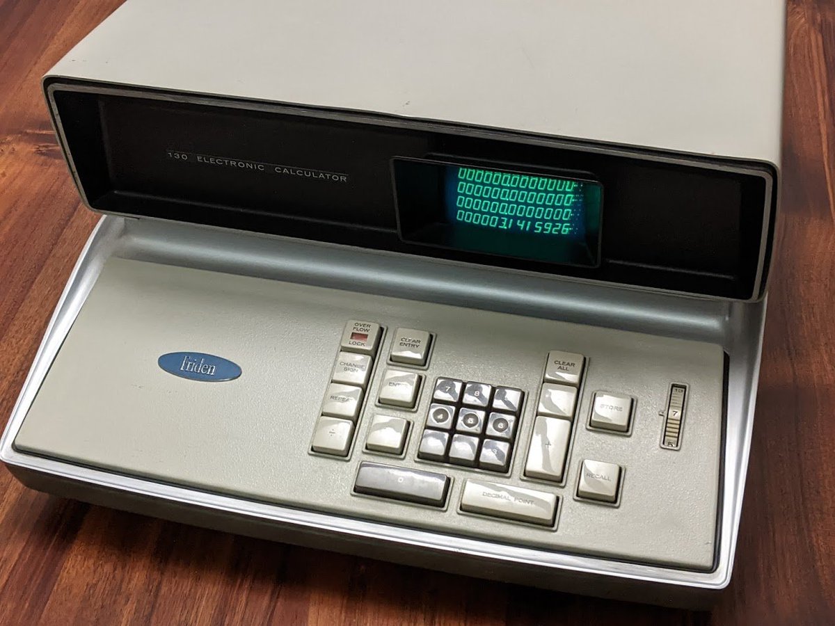
you could buy it for about $2100 back then (about $20K now!) isn't it pretty though?
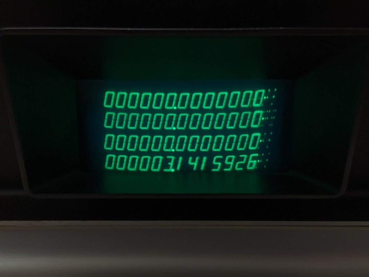
let's take a closer look at the screen. these are not LEDs or vacuum fluorescent displays, this is actually a CRT!
the keyboard is gorgeous, with large mechanical keys that feel very good to the fingers.
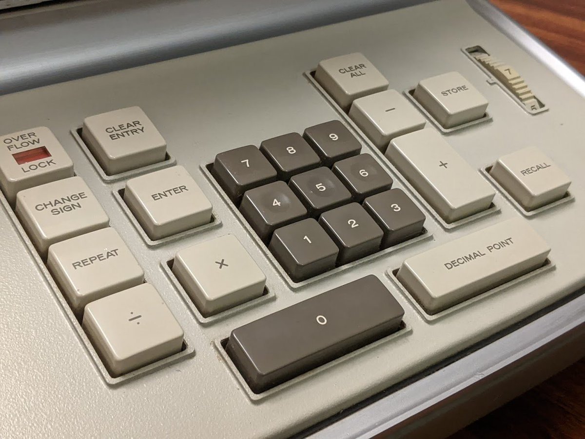
the keyboard has an internal solenoid so that if you have an overflow condition, it *physically* locks up several buttons so you can't continue to enter data until you clear the overflow!
in fact, the keyboard does not support rollover and has a mechanical mechanism inside that prevents multiple keys from being pressed at the same time.
the same solenoid mechanism also prevents you from entering data while it is performing a calculation. you'd think it would be easier to do this digitally, but i think Friden wanted to make the user experience similar to the old mechanical adding machines.
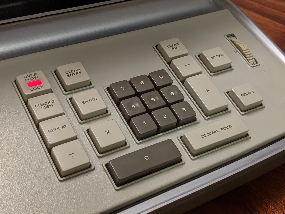
someone spent a lot of time designing the these buttons. i love how the indicator LED is just bright enough to attract your attention without being blindingly bright.

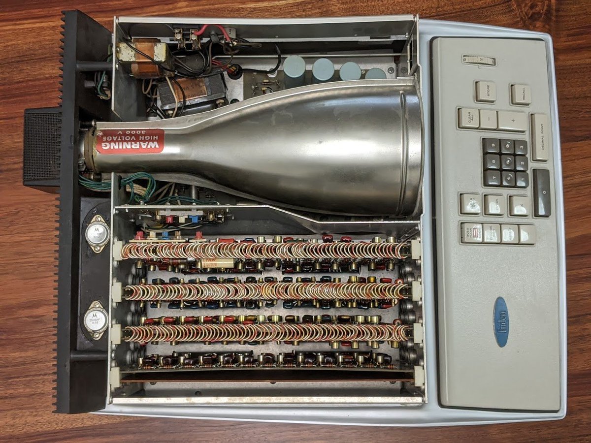
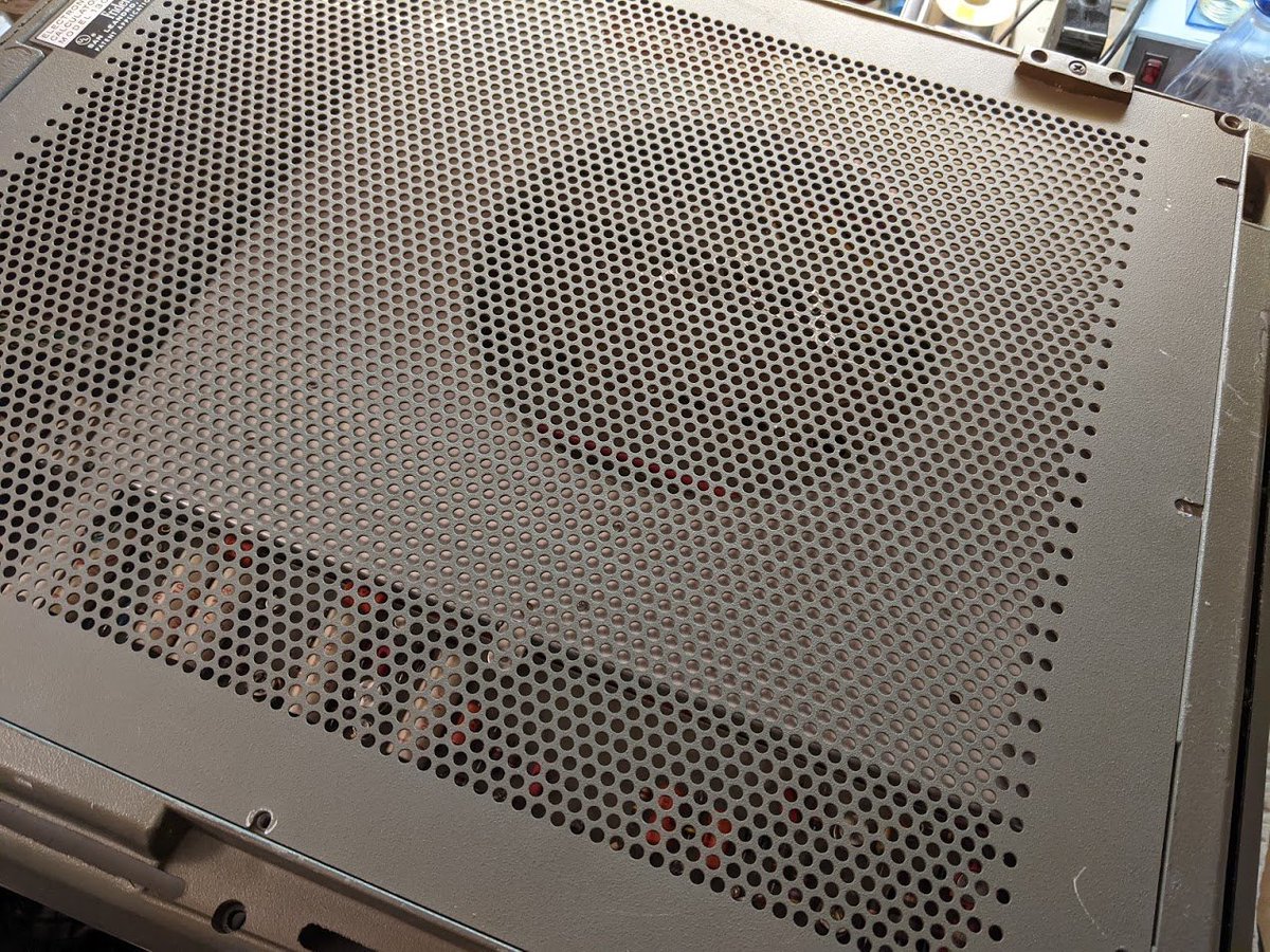
to remove the lid, you loosen two screws underneath near the rear of the case, and two pins come down, allowing the whole lid to slide forward and come off. inside are some circuit cards and a very large magnetic shield over the CRT.
i was experimenting a bit with these adjustment potentiometers which control how the numbers are displayed on the CRT. let's take a closer look, it's quite fascinating!
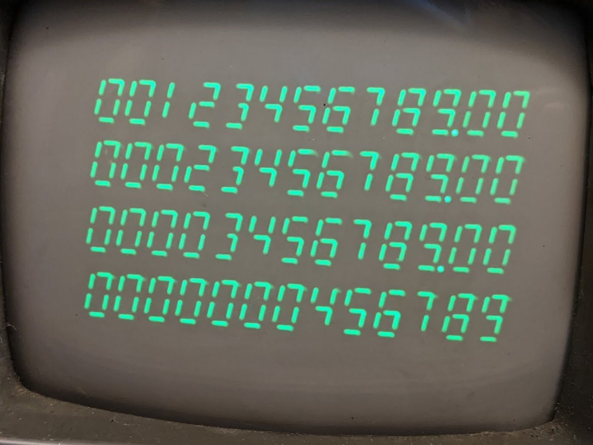
here are the numbers up close. they are basically just line segments. if they look a lot like 7-segment displays...
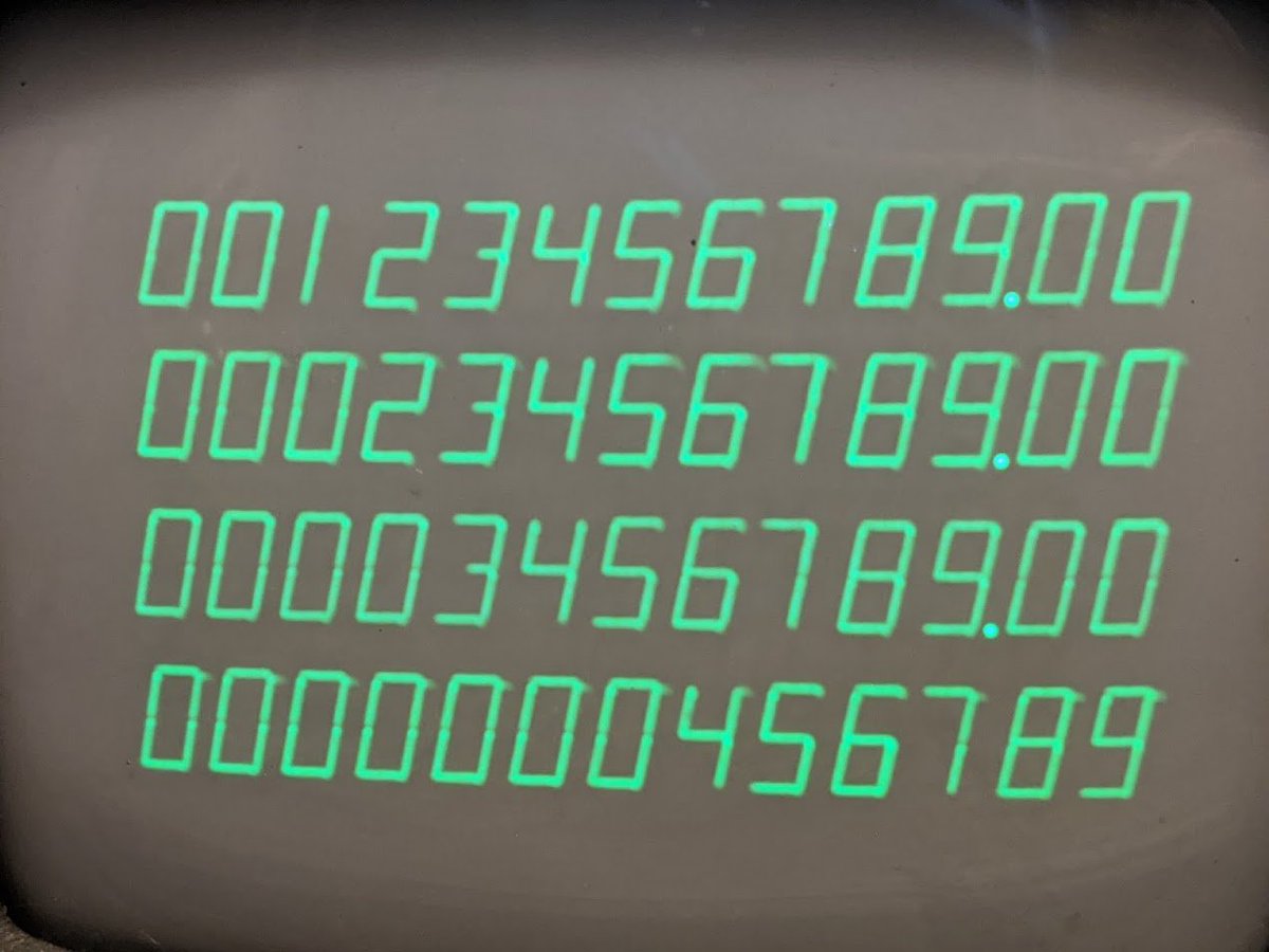
...that's because they are! i turned an adjustment pot which separated the segments from each other a bit more. it's a bit harder to read this way, but you can see it's exactly like a regular 7-segment display.
how does all this get generated? well, @babbageboole reverse engineered most of the schematics of this thing, and it uses some clever transistor circuits to do it. it creates a pattern of dots which can be turned into vertical or horizontal lines.
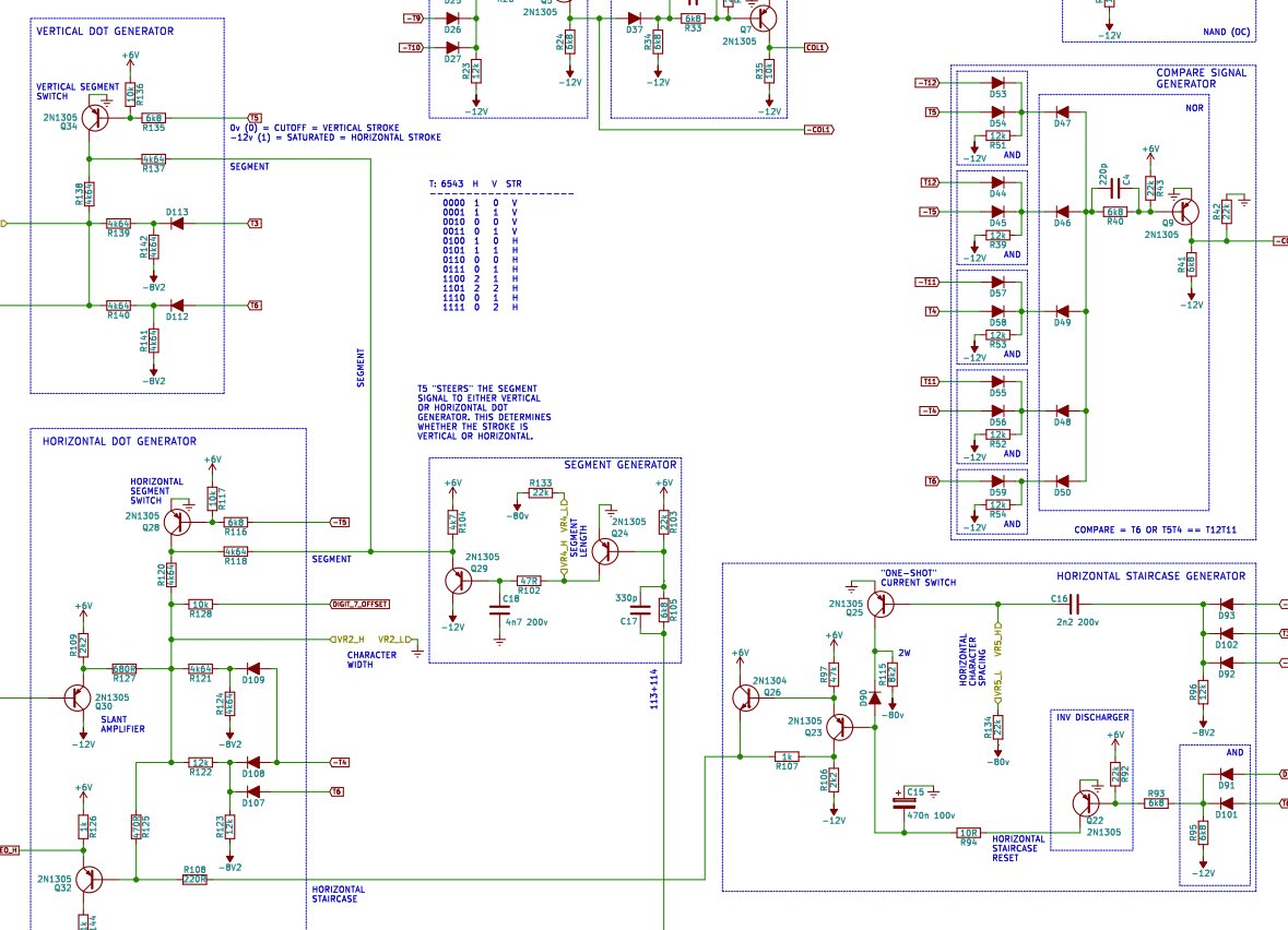
to position the dots, the device uses two very simple DACs as staircase generators. the inputs come from timing flip flops. this positions the electron beam on the screen.
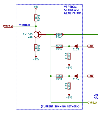
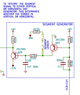
the segments are made using this ramp generator (which can be horizontal or vertical). the segment length there refers to a potentiometer. i adjusted this one in order to exaggerate the CRT image previously.
so how does the calculator know which segments to display for a particular digit? remember, the whole calculator just uses discrete PNP transistors!
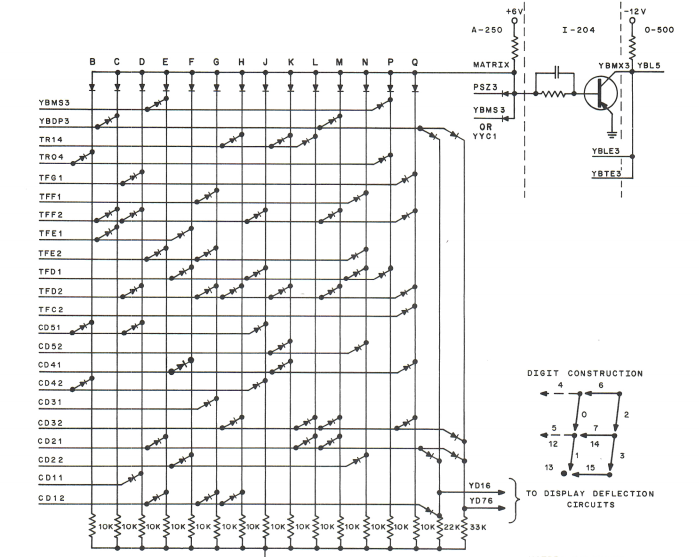
it uses this crazy diode ROM! i don't fully understand how it works since i haven't had the time to study it, but it's not really binary or BCD in the regular sense...
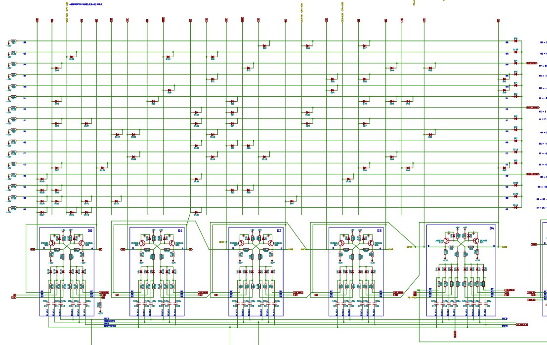
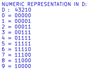
it seems that each digit is represented using this 5 bit code. it's not quite Gray code. i don't recognize it but perhaps one of you can tell me what it is.
there are a lot of these two-transistor latches (aka bistable multivibrators) in this calculator. the inputs are ORed together using diodes.
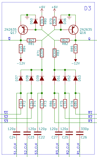
oh yeah, the logic levels are a little strange too. here's a NAND and an inverter. logic '0' is -12V and '1' is 0V. you can probably trace through and figure out how it works.
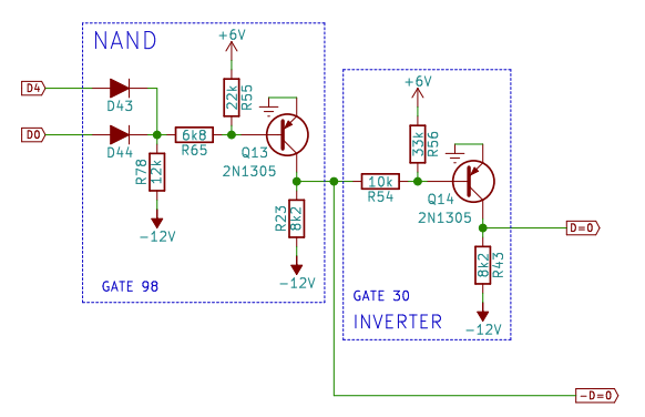
i think the reason for the logic levels is that all the transistors are PNP, which were the most common and least expensive at the time.
another circuit that stood out to me is the -3000V power supply that is used to bias the CRT's cathode. it's got a little oscillator with a transistor driving a transformer, and the AC output of that goes through a Cockcroft-Walton voltage multiplier circuit.
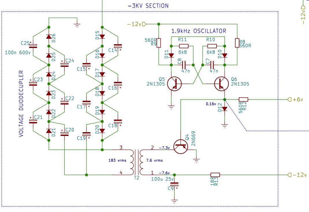
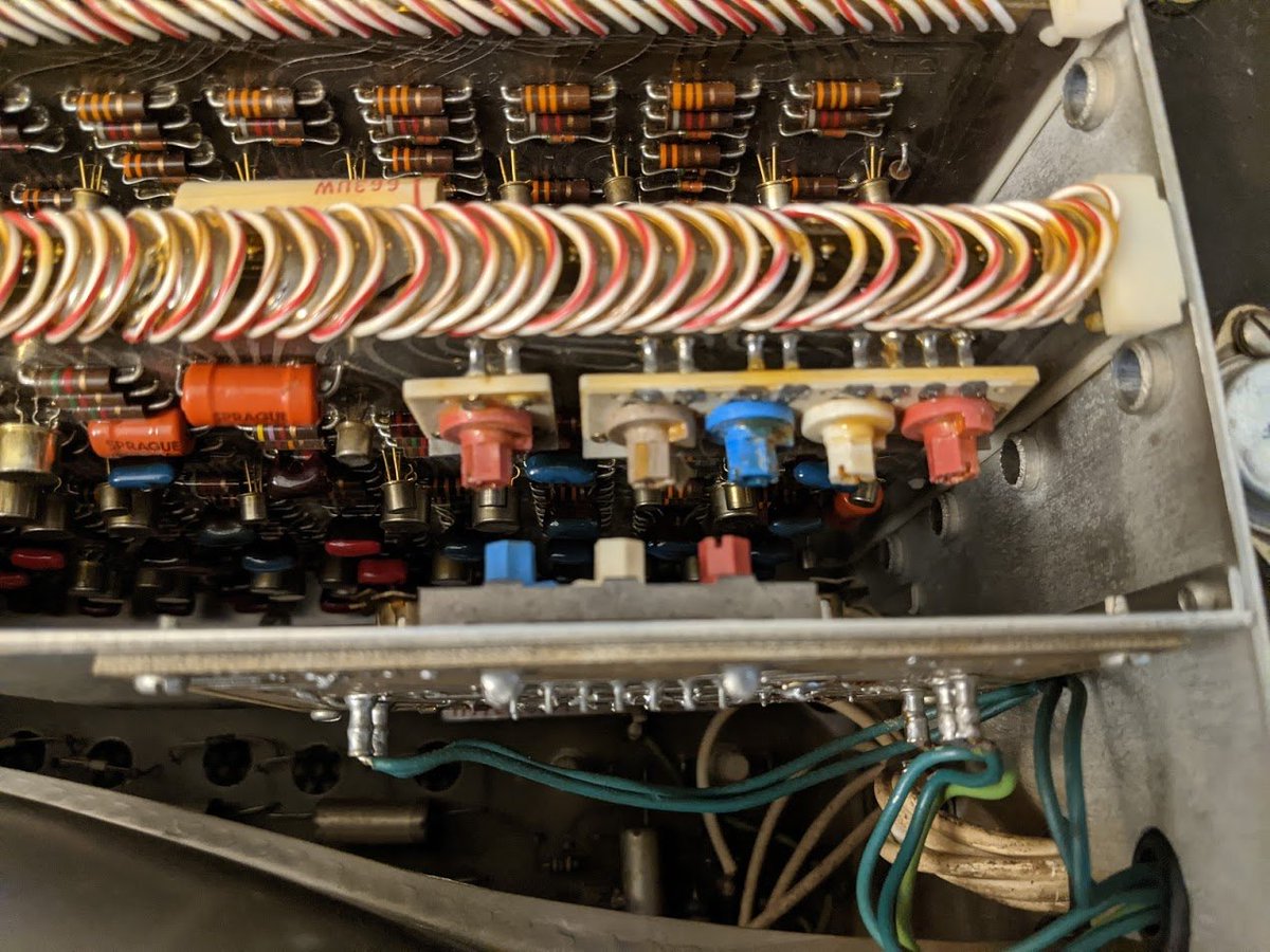
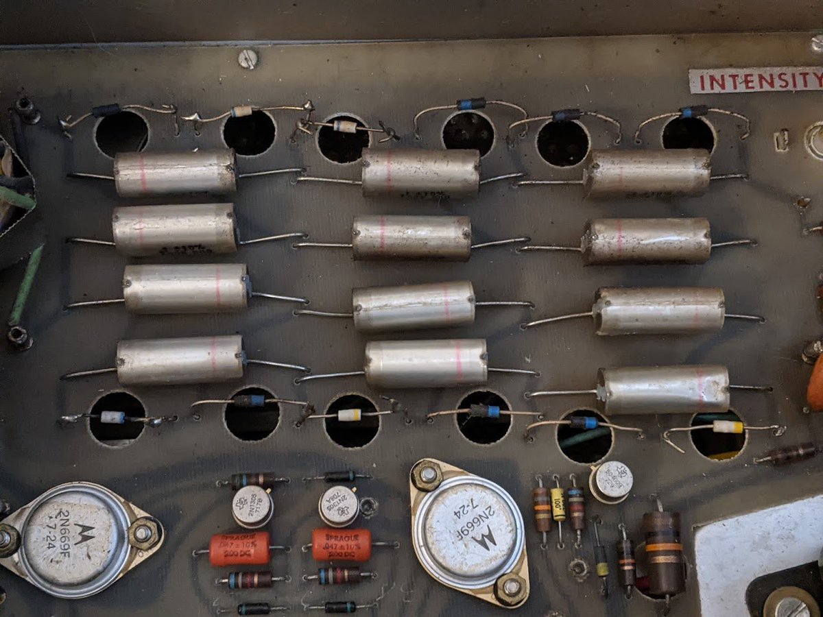
you can see the multiplier circuit rather easily on the circuit board underneath the CRT. those are some pretty large film capacitors!
so the calculator memory stores four 13-digit numbers. if each uses 5 bits, then it would need 260 latches or 520 transistors.
except there aren't 520 transistors in this calculator. what's going on?
except there aren't 520 transistors in this calculator. what's going on?
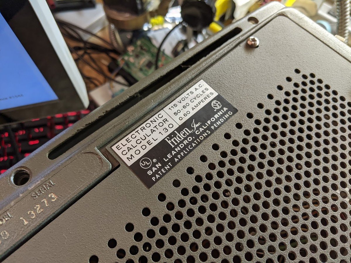
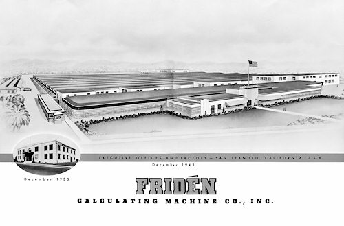
let's take it apart some more, from underneath this time. ooh, nice label! looks like this calculator was probably manufactured in San Leandro.
hmm, not a bad looking factory! like lots of other factories from this era, it later became a hazardous cleanup site due to TCE and other contamination.
where was i? oh yeah, taking the lid off underneath.
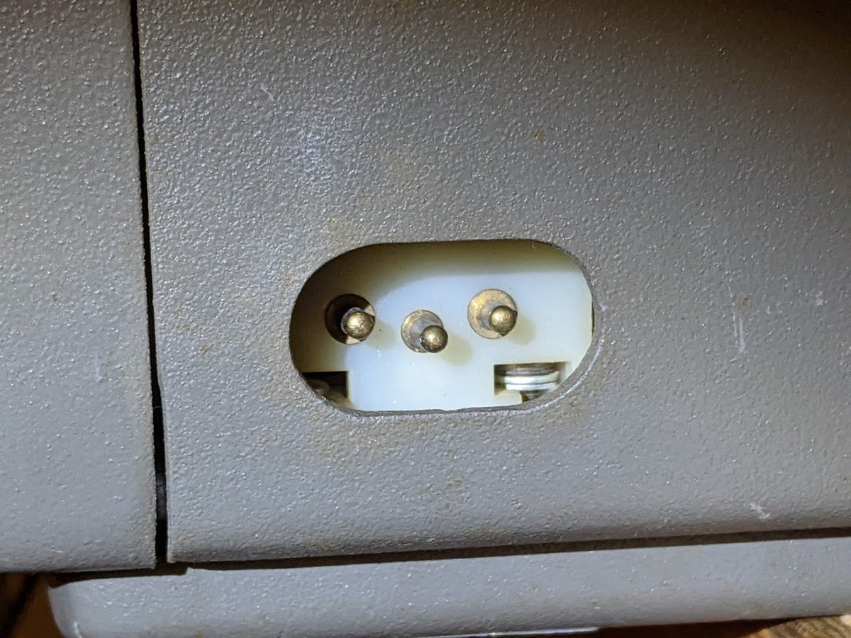
ok, what is this strange thing with a large round hole in it?
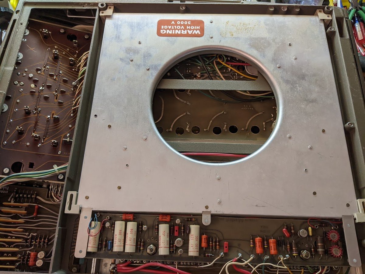
let's take it apart and find out! (this is not my photo, my unit was riveted together, and i didn't feel like needlessly drilling out the rivets in a collectible calculator.)
what are we even looking at? a spiral of wire?
what are we even looking at? a spiral of wire?
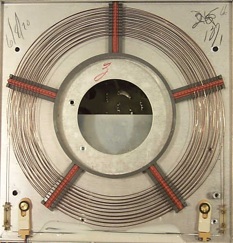
turns out, this is a *magnetostrictive delay line* being used as a serial memory!
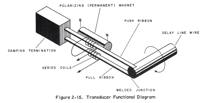
the way it works is that there's a little transmitter coil that imparts a torque (twisting) motion on the wire, and at the other end of the wire is a little receiver coil that picks up the twisting motion. the wire is coiled in a spiral so it takes up less room.
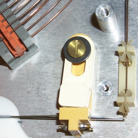
there's an amplifier circuit that takes the pulses coming out and then feeds them back into the input. so any pulses that you put on the wire run around and around and around...
this is because it takes a few microseconds for a pulse (converted to a tiny twisting motion) to make it from one end of the wire to the other.
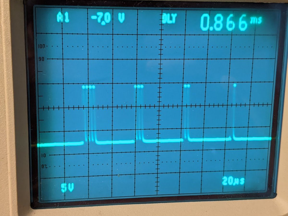
let's look at some pulses. a single "bit" is a positive+negative pulse. how do you store information though?
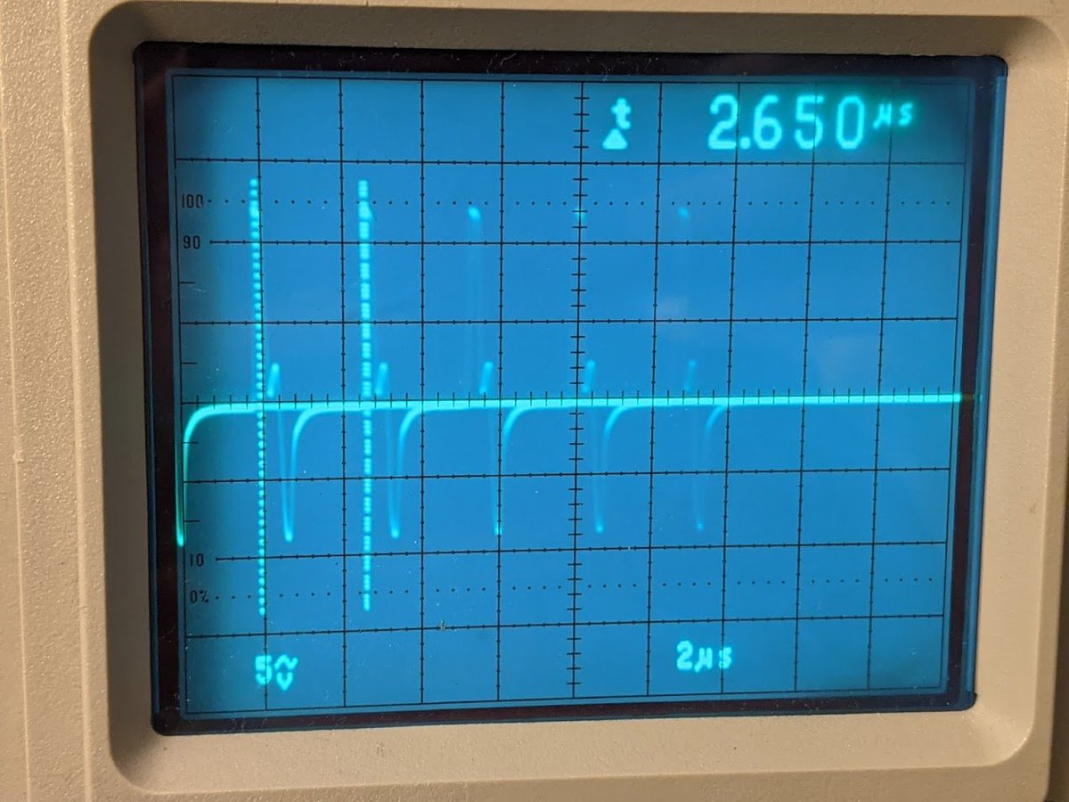
you encode it! the bit order starts with digit 0 of the top register, then digit 0 of the register underneath that, and all the way down to digit 0 of the bottom register. here i have stored the numbers 4, 3, 2, and 1. so the number is stored as the number of pulses!
(digits 1 through 12 are stored after this in sequential order)
so this means that all the calculations must be done one digit at a time, and it all has to be synchronized with the display and the keyboard.
this memory is not a RAM because it does not allow random accesses. you have to wait until the digit you want to access comes around.
special thanks to the previous owner of the machine, @babbageboole, who did some very tedious reverse engineering work to arrive at partial schematics available at github.com/RobertBaruch/F…
and yes, Rob, i found period-correct replacement neon lamps for the ones that broke off in the power supply circuit.
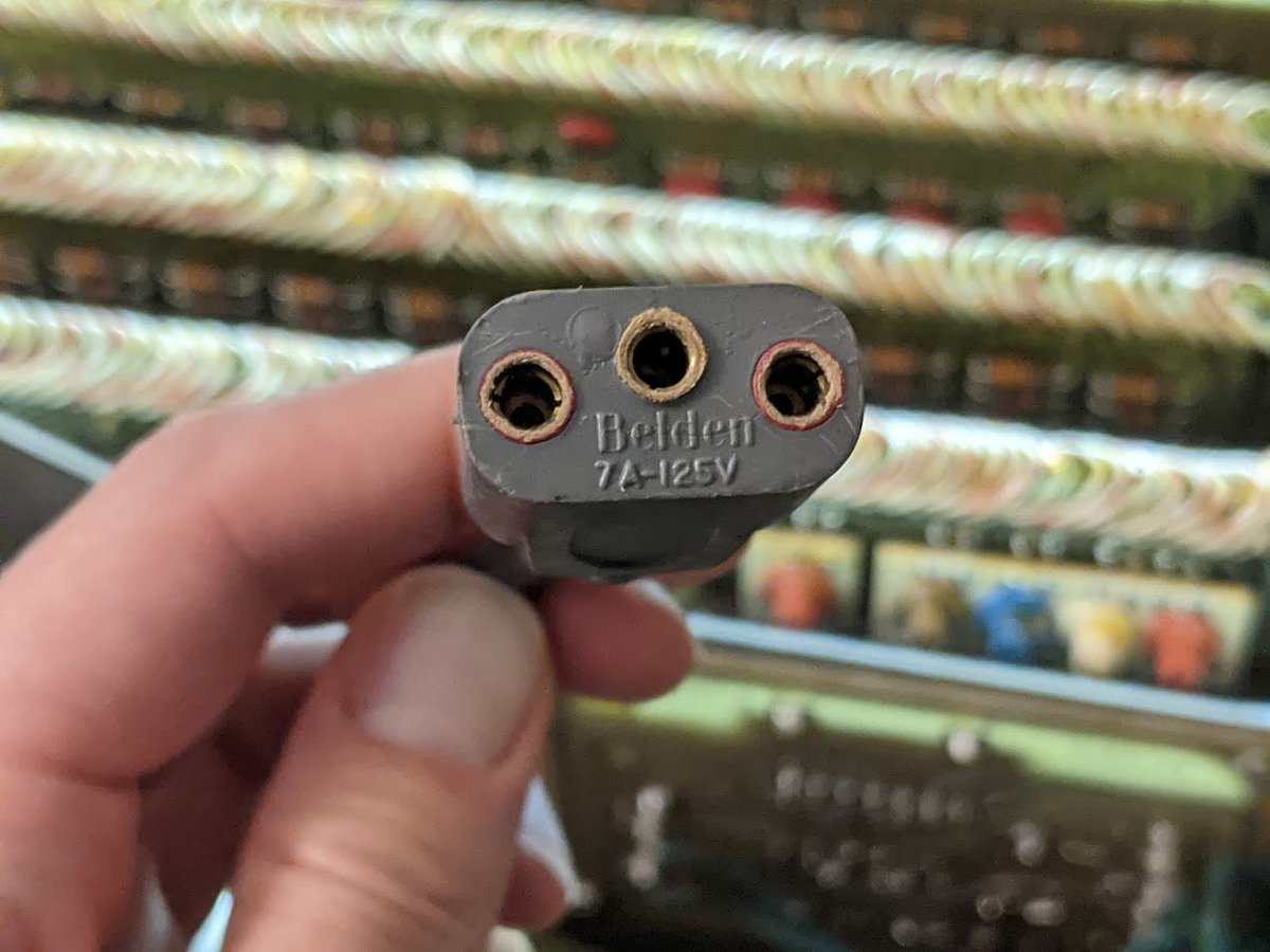
i also found a period-correct power cord in my stuff.
it turns out the original schematics exist, and @bitsavers tweeted about them a while back.
https://twitter.com/bitsavers/status/1202096509942214656
the Old Calculator Museum has a lot more information on this fascinating piece of vintage technology.
oldcalculatormuseum.com/friden130.html
oldcalculatormuseum.com/friden130.html
go there to learn all the details about the people who designed the machine, both at Friden and at Stanford Research Institute, who developed the beautiful CRT display. they were very smart people who were involved with all sorts of other groundbreaking projects!
all the technical details on the magnetostrictive delay line can be found in the original engineering report
oldcalculatormuseum.com/d-f130dleng.ht…
oldcalculatormuseum.com/d-f130dleng.ht…
earlier i called this an "LED." it is not, i mistyped. this is likely a neon bulb but it could also be an incandescent light bulb. LEDs weren't common until the 1970s and were quite expensive at first.
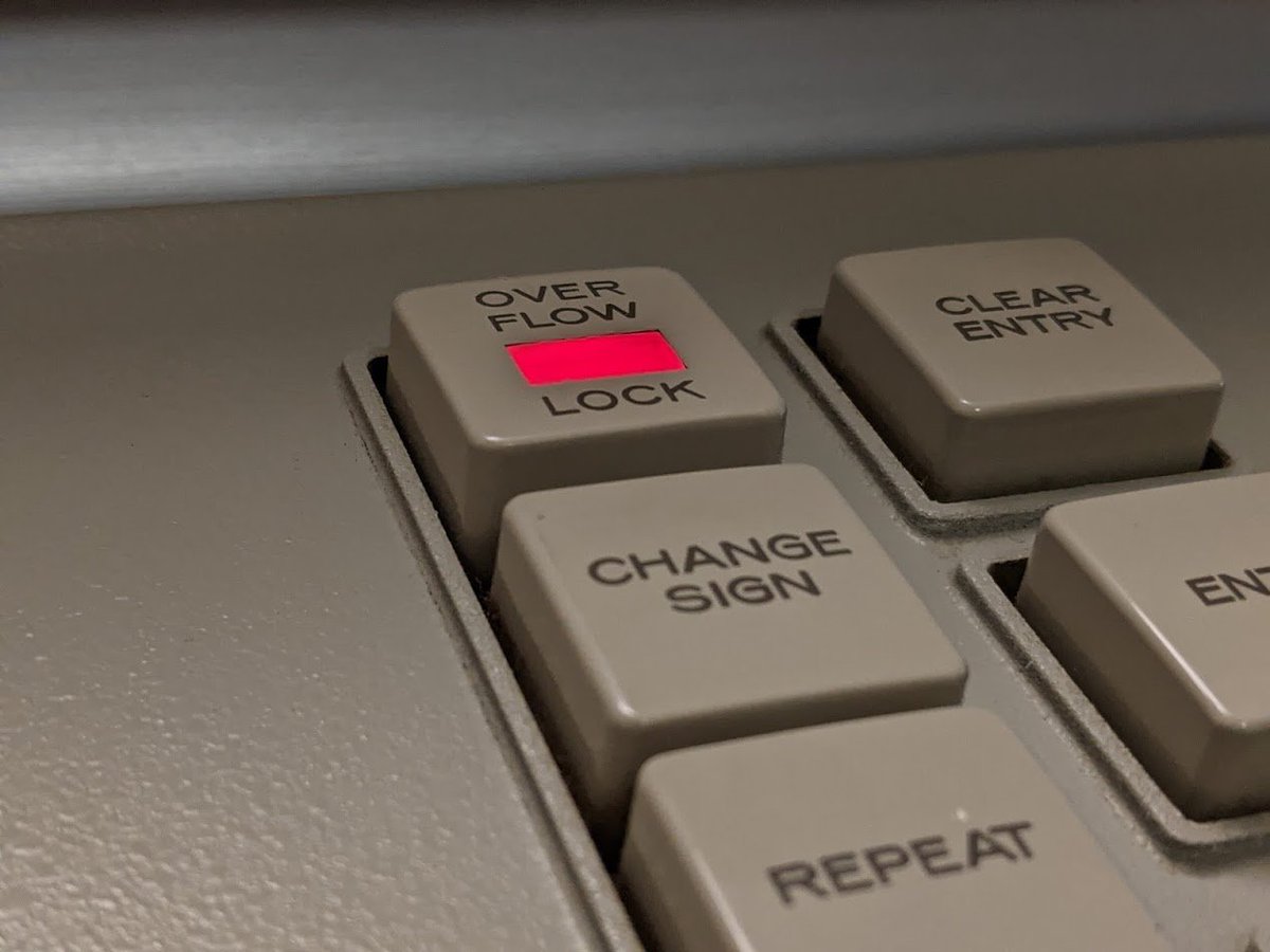
i wanted to say "lamp" or indicator or whatever but my fingers betrayed me and typed "LED". then later when 28,938 people were saying "it's not an LED" i thought "of course it's not, this is 1964, why would you think it is?" and then i read my original tweet. 🤦
the service manual is available online, and it discusses how the calculator works!
oldcalculatormuseum.com/m-f130service.…
oldcalculatormuseum.com/m-f130service.…
it has some nice diagrams, like this one which shows how the transducer creates a torque in the delay line wire.
or how about this chart showing how the digits are formed for the display?
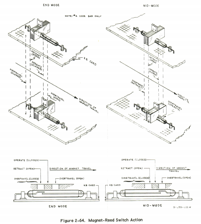
looks like the keyboard uses reed switches.
• • •
Missing some Tweet in this thread? You can try to
force a refresh