Clamp, link, pulley: the 3 headspan genders (a #railwaysExplained thread)

A few of the #OLEbook images are a bit meh. So yesterday I went out on a trip to West Ealing to pick up some better ones. In this case, headspan supports.

But 1st, a refresher on along-track movement

1/
All OLE systems have to deal with the phenomenon of along-track movement - the amount of expansion and contraction the wires experience as wire temperature varies, due to ambient heating/cooling from solar gain and wind, and also current heating due to electrical load

2/
All modern mainline systems deal with this by using auto-tensioning; a device is provided at each end of the wire which provides a constant tension. Weights or springs are used, & the wires are able to expand / contract around a fixed central point - the midpoint anchor (MPA)

3/
Obviously this movement must be allowed for in the design of the supports at each OLE structure. For a system using cantilever and/or portal structures, the MPA is simply a back-to-back catenary anchor, & along-track movement is dealt with by having pivoting cantilevers

4/
But what about railways using headspans? These structures have no steel boom to fix an MPA to, or cantilevers that have a convenient place to insert a pivot.

Enter the clamp, link and pulley arrangements

5/
First, lets deal with the MPA. This is essential to stop the wire run migrating along the track, and under a broken wire scenario the loads increase dramatically.

6/
The flexible nature of the span wires means that no single headspan can resist the load from the MPA - especially under the broken wire scenario.

So instead the catenary wire is clamped to the headspan at 5 consecutive structures at the middle of the tension length

7/
Now that we've fixed the MPA, the wires will expand and contract around it. But that means movement. The further you are from the midpoint, the more movement.

So the next few structures either side of the clamped structures have links. These swing to allow a bit of movement.

8/
As we move even further from the MPA, the movement is too much for a link - at the tensioner end movement can be up to 1.5 metres. So a pulley is provided instead.

9/
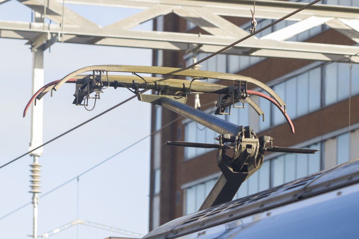
These pulleys can cause problems; the bearings can seize, and the resulting sawing action will break the wire & bring the whole lot down. So in the picture above the catenary hangs below the pulley & a more robust stainless steel bridle supports the catenary over the pulley.

9/
In modern systems we try to avoid using pulleys altogether - one of the reasons we tend not to use headspans. But sometimes even on portal systems, clearances are too tight for a cantilever. Modern pulleys are smaller, so rotation is greater & seizure less likely to occur

10/
That concludes my TED talk I'll take questions now

ends/
postscript: another component that I have on my "must improve" list is a line guard. See this thing here? It's a line guard.

That's right, I did a 2 hour trip to West Ealing, didn't notice the lineguard till I got home, didn't get a proper img. Will have to go back!
If you enjoyed this thread there are plenty more here btw:

• • •

Missing some Tweet in this thread? You can try to force a refresh
 

Keep Current with Garry Keenor (He/Him)

Garry Keenor (He/Him) Profile picture

Stay in touch and get notified when new unrolls are available from this author!

Read all threads

This Thread may be Removed Anytime!

PDF

Twitter may remove this content at anytime! Save it as PDF for later use!

Try unrolling a thread yourself!

how to unroll video
  1. Follow @ThreadReaderApp to mention us!

  2. From a Twitter thread mention us with a keyword "unroll"
@threadreaderapp unroll

Practice here first or read more on our help page!

More from @25kV

7 Jun 20
@alanlmsca @poggs @partialcontent @WillDeakin1 @petemashmorgan @jamesjefferies Lets look at that idea.

RTC were very good at learning from R&D done in other sectors. e.g. the APT having a body structure derived from aircraft design.

1/
@alanlmsca @poggs @partialcontent @WillDeakin1 @petemashmorgan @jamesjefferies In this case they'd be looking at the work done by the automotive sector on EVs. Automotive has far larger buying power than rail.

With all of that R&D effort over the last 10 years, they have managed to create batteries with an energy density of ~1/5 that of diesel fuel

2/
@alanlmsca @poggs @partialcontent @WillDeakin1 @petemashmorgan @jamesjefferies So that means that - to cover the distances a train does - an entire vehicle, maybe more, would need to be given over to batteries. And that affects the economic case because trains are all about BUMS ON SEATS and so the effective train length just reduced

3/
Read 9 tweets
18 Apr 20
THREAD: A few of you requested a #railwaysExplained thread Return Conductors (RCs) and Auto Transformer Feeders (ATFs). As part of that I'll be attempting to explain how immunisation works. HEALTH WARNING: this will involve electromagnetism. Apologies in advance!

1/ ImageImage
Lets start with the very basics: overhead line forms part of an electrical circuit. Just like all circuits, the electricity flows out from a supply (the feeder station) to the load (the train) and then flows back to the supply. The OLE forms the outward leg of the circuit

2/
The simplest way to form the return half of the circuit is simply to use the running rails. Connect the non-OLE side of the train motor to the wheels, current flows through the wheels and into the rail, then back to the feeder station.

3/ Image
Read 47 tweets
14 Nov 19
THREAD: some of you might be wondering what the hell this train is. I'll try to explain that, while touching on some of the wider requirements for testing new #OLE for entry into service #railwaysExplained

1/

This is an OLE test train that's been put together by the @networkrailwest electrification project team. The train is intended to undertake mechanical and electrical testing of the OLE between Bristol and Cardiff in advance of entry into service

2/
The mechanical testing is performed using the pantograph on top of the class 90. It is unusual in two ways: 1) it carries force & acceleration sensors so that it can measure contact force, and 2) it is the only cl 90 carrying an HS-X pan, the type used by @GWRHelp at 125mph

3/
Read 29 tweets
24 Oct 19
THREAD: Every so often during a discussion about electrification at bridges, the subject of COASTING comes up. I denigrate the idea without explaining why, then move on. I've been meaning to do better than that for a while: so here it is, buckle up!

1/
Let's start by defining coasting as follows:

Coasting is when an electric train passes through a section of railway without taking power, using only its own inertia to make it through the gap.

2/
Things that AREN'T coasting:
1) a bi-mode train switching from electric to diesel
2) A train switching to batteries that were charged while the train was under OLE
3) Hydrogen or other vapourware

3/
Read 46 tweets
12 Aug 19
THREAD: recently @EurostarJustinp and @EurostarGeorge mentioned windspeeds in relation to #OLE design. In response I promised them a thread on #wind.

No sniggering. Yes, you at the back. I saw you. STOP IT

This is that thread.

1/
OLE is exposed to a number of enviro factors, and wind is one that we spend most time worrying about. It's common for industry types to jokingly refer to OLE as "the wind-blown wobbly wire" - and there is some truth in that.

But wind affects a lot more than just the wire...

2/
…but lets deal with the wire first. OLE must be kept within specific horizontal limits relative to the pan - and therefore to the track. Broadly, in the UK, the wire must ALWAYS be within 400mm of the track centreline.

Doesn't sound too hard does it? THINK AGAIN DEAR READER
3/
Read 25 tweets
7 Apr 19
THREAD: Nice sunny day, so off to the garden centre. What's that you say? The UK's only open air section of Rigid Overhead Conductor Bar is just down the road, between Patchway Old and Short Tunnels? Oh go on then.
You might be wondering why it has been done like this. Both tunnels are too low / arch too cramped to fit conventional OLE, So ROCS is used instead. Normally you would transition back to conventional OLE outside the portal. But here the distance between portals is too short.
By the time you got back to conventional, its time to transition again. No point in doing that. So the only real option is to continue the ROCS in open air.

One major downside of ROCS is its weight - it needs supporting every 12 metres to stop it sagging. Hence the sea of masts.
Read 7 tweets

Did Thread Reader help you today?

Support us! We are indie developers!


This site is made by just two indie developers on a laptop doing marketing, support and development! Read more about the story.

Become a Premium Member ($3/month or $30/year) and get exclusive features!

Become Premium

Too expensive? Make a small donation by buying us coffee ($5) or help with server cost ($10)

Donate via Paypal Become our Patreon

Thank you for your support!

Follow Us on Twitter!

:(