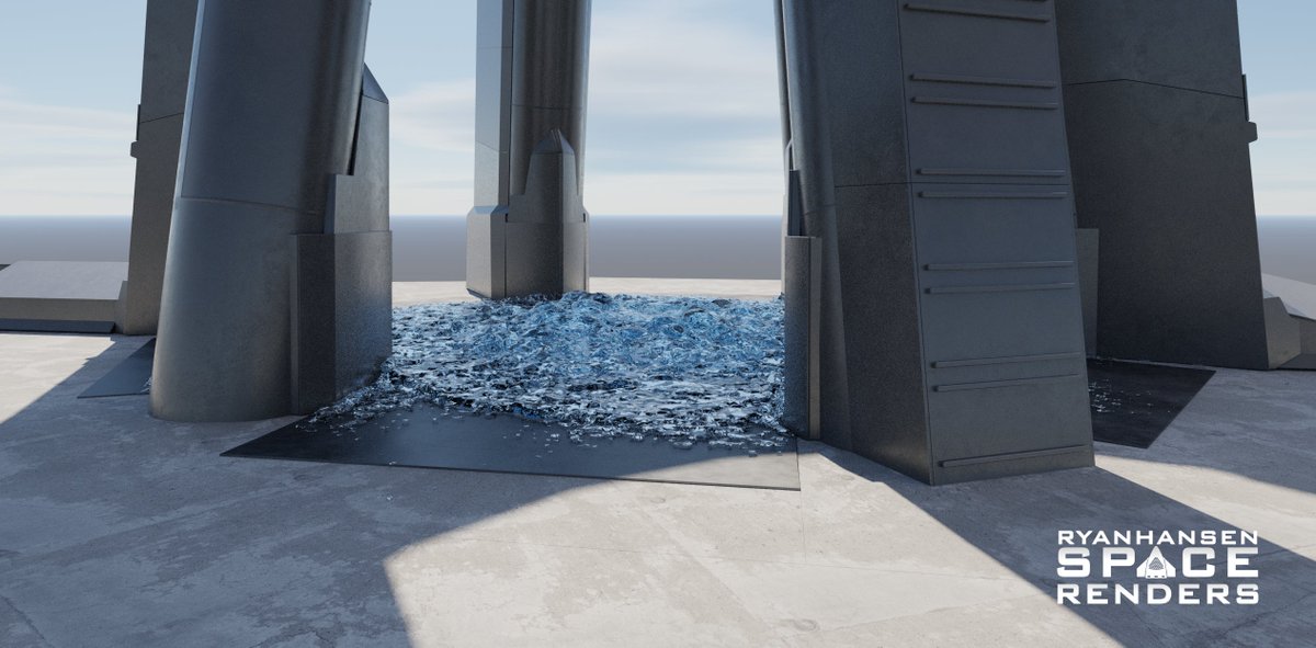
There have been many questions and concerns about the water-cooled steel plate that is planned to be installed under the OLM. I’ll go over some details about it in this thread and maybe ease some of the concerns. There will be some speculation in this towards the end. (1/n)
The term “water-cooled plate” is a bit misleading for people who don’t understand how the system will function. Many may relate this system to a closed-loop water loop used on some high-end gaming computers or the liquid intercooler system used in high-performance vehicles. (2/n)
While water will run through the plates, the main cooling effect comes from holes that will “leak” water onto the surface of the steel. This is required as it cools the metal surface and absorbs energy from the plume at the same time. There are other advantages as well. (3/n)
Releasing the water from the plates means you don’t have to worry about it boiling inside the plates and producing steam. The top plate is thick enough that it does not transfer heat fast enough for the water running through the plate to turn into a gas. (4/n)
@StarbaseSim has done a few simulations to show the heat transfer over time when estimating the heat load of #SuperHeavy. You can find those results linked below. (5/n)
From @StarbaseSim’s results we can determine that water will be needed on the surface of the steel to form a barrier between the plume and steel to keep it from reaching melting temperatures. This is where the transpiration effect of the water comes into play. (6/n)
Elon has previously spoken about a “showerhead” design that would provide water under the OLM. As some have pointed out, the water would need to be at a higher pressure than the pressure created by the #SuperHeavy Raptor engines under the OLM. (7/n)
Also talked about is the possibility that the high-pressure water could create a high-pressure fountain from all the holes that could affect the #SuperHeavy booster and Raptor engines. This is possible but may not be a concern in some situations with careful control. (8/n)
Nonetheless, I decided to come up with a possible solution for this that helps protect the #SuperHeavy booster and also promotes better cooling of the steel plates. This is getting into speculation territory so this is merely ideas and not something that has been seen yet. (9/n)
Each hole could have a diverter that directs the water horizontally instead of vertically. High-pressure water traveling horizontally will help create the water barrier between the plate and plume talked about earlier. These caps are also cooled by the water around them. (10/n)
Another benefit of the diverters is they can seal the plates when not in use to prevent FOD. Gravity can pull the caps shut when no pressure is pushing from the inside. When water is fed into the system the pressure can push the caps up allowing for water to escape. (11/n)
I went as far as modeling up a mock plate and feed tube to run some water simulations of my own to show the difference that the diverters can provide from a conceptual point of view. This is a screenshot from an animation available in the latest @CSI_Starbase episode. (12/n)
As of right now much of this plate design pictured is still speculation. We have bits of information to create assumptions from but much of the hardware has yet to be assembled or arrive on site. I will continue to follow this and update details as they become available. (13/n)
For more details and animations showing the water simulations I’ve talked about here be sure to check out the link below! This episode by @CSI_Starbase digs into many details of the OLM and the first launch of #Starship. (14/n)
• • •
Missing some Tweet in this thread? You can try to
force a refresh
The #Starship #SuperHeavy Booster Quick Disconnect (BQD) has been one of the most difficult Starship-related items to model due to its geometric complexity. The BQD operates primarily using only 2 pistons at the base of the structure to push or pull on the parallel frames which moves the BQD interface (and associated hardware and hoses) and operates the door through several linkages making this system as simple as possible from a controls standpoint. 1/5
Recently, the BQD received a new door. This new door features an additional protrusion allowing for additional space under the door. It was originally thought this could be for extra strength as the original door seemed to warp after a few launches. I had a different opinion and alluded to the purpose of this protrusion on @RGVaerialphotos Starbase Weekly, Ep.114. After reviewing many reference images taken by @StarshipGazer I have determined what this new protrusion and hardware is for and modeled it the best I can given the limited views we have of the hardware. 2/5
This new hardware adds a mechanism to the BQD door with several black discs that move to seal the GSE ports on the BQD interface when retracted back into the hood. This should help mitigate Foreign Object Debris (FOD) from getting into the pipes during liftoff and when the BQD is not in use. It is impossible to see the backside of this mechanism so the placement of the pistons is an educated guess. 3/5
Shortly before I posted my first detailed thread about my #SuperHeavy #B9 propellant simulation results, #SpaceX rolled B10 to the launch site, and some new weld marks were observed in the lower LOX tank. Like others, I also speculated this may indicate new slosh baffles. /1
It appears SpaceX determined the existing baffles within the LOX tank aren’t enough to mitigate slosh at staging. Using the weld marks, I devised a few designs and tested them with the same conditions as the previous thread to see how each design would change the liquid behavior. /2
Before looking at any new simulations, let's look at the original side cutaway. I will be using this angle and animation throughout this thread to make comparisons. Also, keep in mind my disclaimer in the previous thread about these results and their theoretical accuracy. /3
Interesting parts are taking shape at #SpaceX's Masseys test site. As more work is completed on the new flame diverter, seemingly random parts start developing into recognizable assemblies. In this short thread, I'll present some ideas surrounding these new parts. As always, this is speculative and subject to change. /1
As always, I do my best to model in detail with accurate measurements from recreated camera shots. Here are my models with one of the images I used from @RGVaerialphotos's recent flyover. Consider becoming a flight supporter as things get more interesting at the Masseys site. /2
First up is the assumed "flame bucket" part of the diverter system. This will be built using 4 pedestals with 6 slots allowing the 6 "C" shaped beams to be attached to form the frame for a curved surface with walls. /3
It's finally time to unveil my #SuperHeavy #B9 propellant simulation results! In this thread, I will
include some animations with data and provide some brief details about the process. I may make another thread explaining this process in more detail at a later date if desired. /1
I started this project the day after #Starship IFT-2 with some basic tests. It took nearly a month to go from a conceptual idea to a workflow that seemed like it could work and produce fairly accurate results with the limited data that onlookers have access to. /2
Simply put, the plan was to recreate the flight path and match the tracking camera angles. Then animate my models to match the motion of B9 and then use that animation data to calculate the 3-axis acceleration of B9 for every frame. Then I could use that acceleration data to drive forces within a fluid simulation. /3
Since my last thread, #SpaceX has made a lot of progress with the upgrades beneath the #Starship OLM. In this thread, I will give an updated look at the transpirationally cooled steel plates and explain how they will all come together as well as some additional speculation. 1/n
If you haven’t seen my previous thread I HIGHLY recommend checking it out first. It has a lot of details that I either won’t mention here or will expand on or correct and it might be confusing without any context. 2/n
Shortly after the first of the year, SpaceX began building different sub-sections. It was clear there would be several different shapes consisting of rectangles, trapezoids, and recently revealed, hexagons. Several different configurations of some shapes were also used. 3/n
SpaceX has made a lot of progress preparing the area around the OLM for the new transpirationally cooled steel plates that will replace the surface below the OLM. I have been observing the changes over the past few weeks and this thread will detail my speculations. 1/n
Note, I model everything with real dimensions that I calculate from pixel-counting reference images. This method is not always perfect but more times than not it leads to mostly accurate conclusions. With that said, this thread has speculation but it's informed speculation. 2/n
Originally I speculated that there would be 6 water manifolds between each leg under the OLM feeding the “steel sandwich” on each of the 6 sides. This aligns with the design used for the new launch mount at 39A which will use a more mature version of this system. 3/n