
#SpaceX has started making some progress on the transpirational steel plate system that will be installed under the #Starbase #Starship OLM. In this thread, I will be detailing the latest findings as well as touching on my process for reverse engineering a system like this. (1/n) 

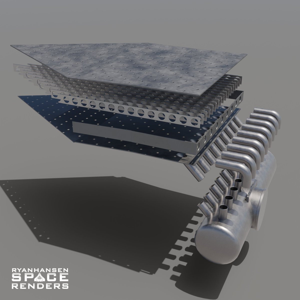
I completely redid all my models related to this system. The supply pipes and manifolds have been measured and accurately modeled. I was able to gather enough reference photos to get many of the dimensions for the plates and have sized those accordingly. (2/n)
A few weeks ago, @RGVaerialphotos captured this photo. At the time, I noticed some of the rectangular plates appeared to have a very slight slant to them. (3/n)

After reviewing many photos from the same flyover I determined that was indeed the case. It can be difficult to get accurate measurements from 10,500ft due to pixel counting limitations so I’d say my dimensions are probably ~95% accurate. (4/n)

At the time I didn’t know exactly how these parts would fit together so my initial models had similar shaped parts assembled roughly how I thought it might look just to get the point across. (5/n)

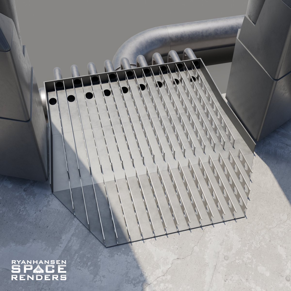
If you look closely, you can see the support walls inside the plate assemblies. The top of each plate has visible weld marks that also indicate the location of the internal walls. There are 17 of these inside each plate. This creates 18 “channels” for water to flow through. (6/n)
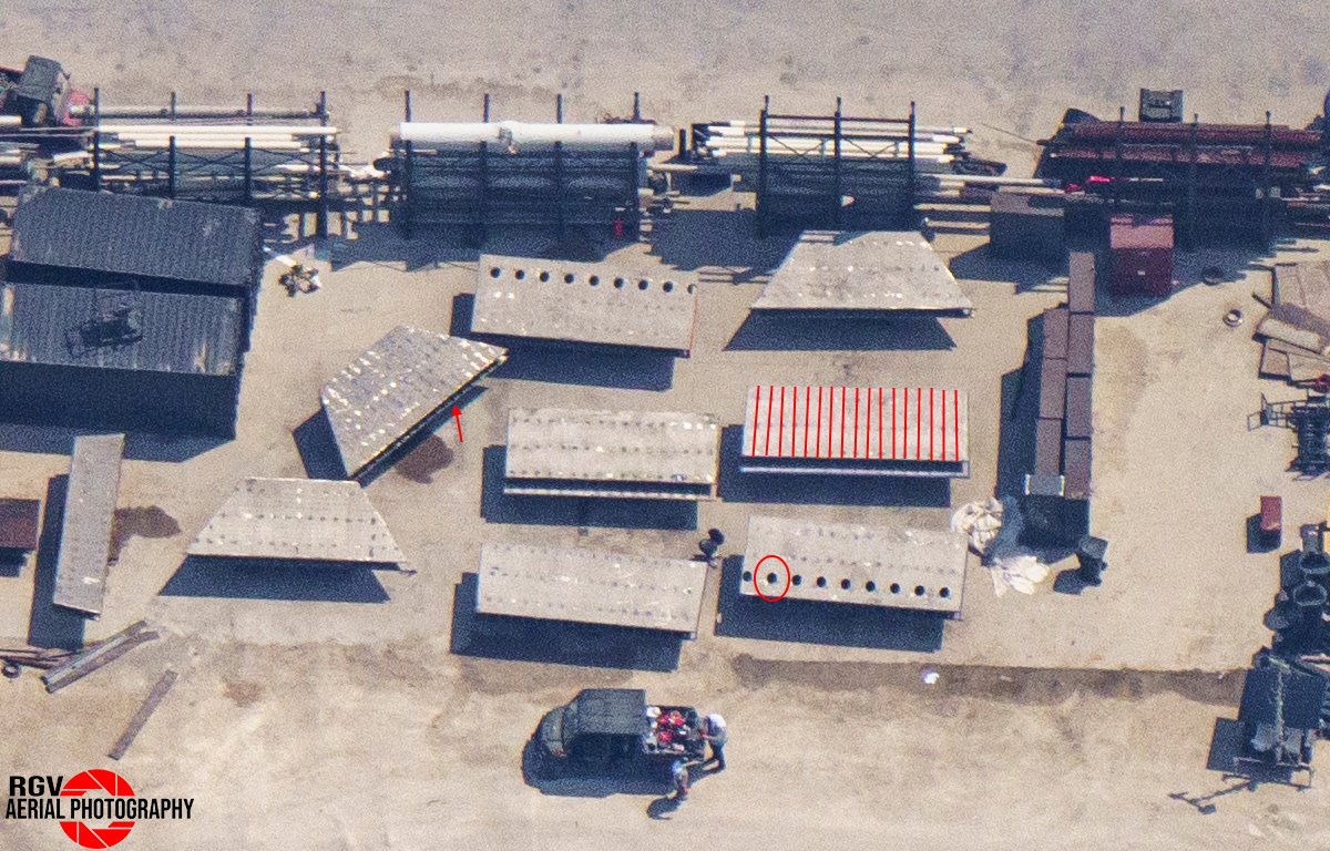
There are 9 holes on two of the plates that happen to fall directly inside 9 of the 18 channels created by the internal walls. One other thing to notice is how the holes appear to be ovular not circular, more on that in a bit. (7/n)

Here are two of the water supply manifolds being assembled. There are two rows of 9 nipples on each manifold. Notice that one row is rotated about ~45°. This implies a total of 18 smaller pipes will be welded to these nipples and feed the plate system, one for each channel. (8/n)
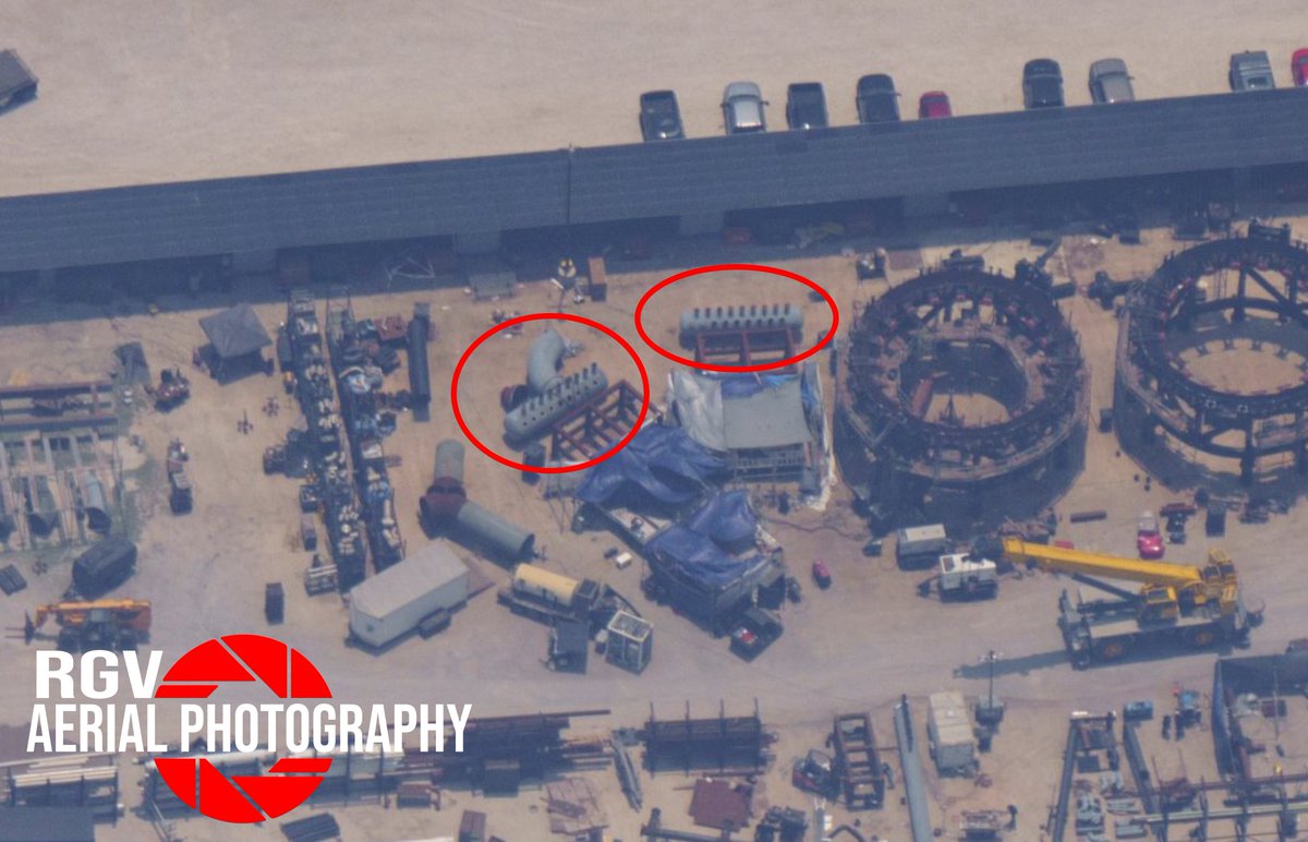
Near the supply manifolds are small sections of pipe. There are straight sections with ~45° cuts on them as well as sections with 90° bends. There are a few different sizes of these parts. I have some theories why but I will wait to talk about that until I see more details. (9/n)

The 9 ovular holes will be connected to the 45° pipe sections and feed 9 of the 18 channels. At the time, there were no indications of how the other 9 channels would be fed but I was able to assume that the 90° pipe sections had to feed the back of the plate. (10/n)

At first, I thought this couldn't be right because it would leave the small 90° pipes very close to the surface but the latest RGV flyover confirms that this is indeed it will be connected. I predict these may be covered with additional steel that is without water. (11/n)
This new RGV photo shows the first set of plate assemblies have been staged over two supply manifolds. At the time of this photo, the plates were not lined up with the but later they were aligned. You can see how all the small pipes will connect the manifold and plates. (12/n)

This also shows how two of the plate sections will be connected together. This shows the rectangular section with the ovular holes has been flipped over and the section with the slight slant to the edges is mated along one side. (13/n)

To model these parts accurately, I find a nearby known measurement and measure the number of pixels. Then I can then use that relation to set up a mathematical ratio. Then I can select any number of pixels and figure out what that distance would be in meters. (14/n)

I did this for all the plates and then modeled them. The longest side of the trapezoidal plate matches the longest side of the rectangular-ish plate. The short edges of the trapezoidal plate form a 60° angle implying that 6 of these plates will fit in a ring under the OLM. (15/n)
Since the short sides of the trapezoidal plates in a ring seem to touch, I can use these as a known reference point to see how everything will sit in relation to the OLM. These are all the known parts visible in their locations. (16/n)

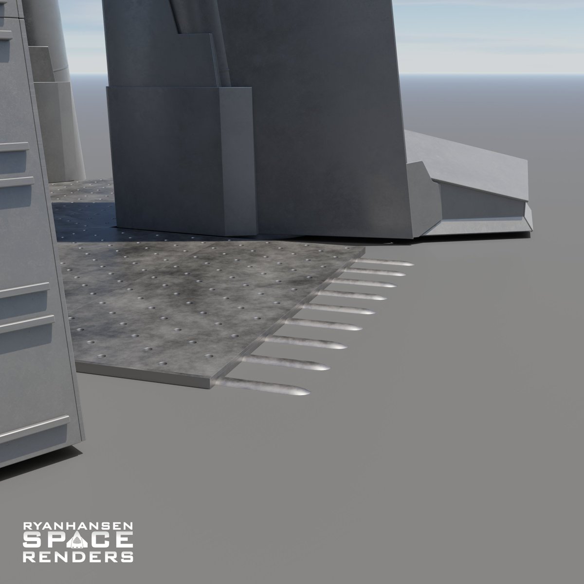
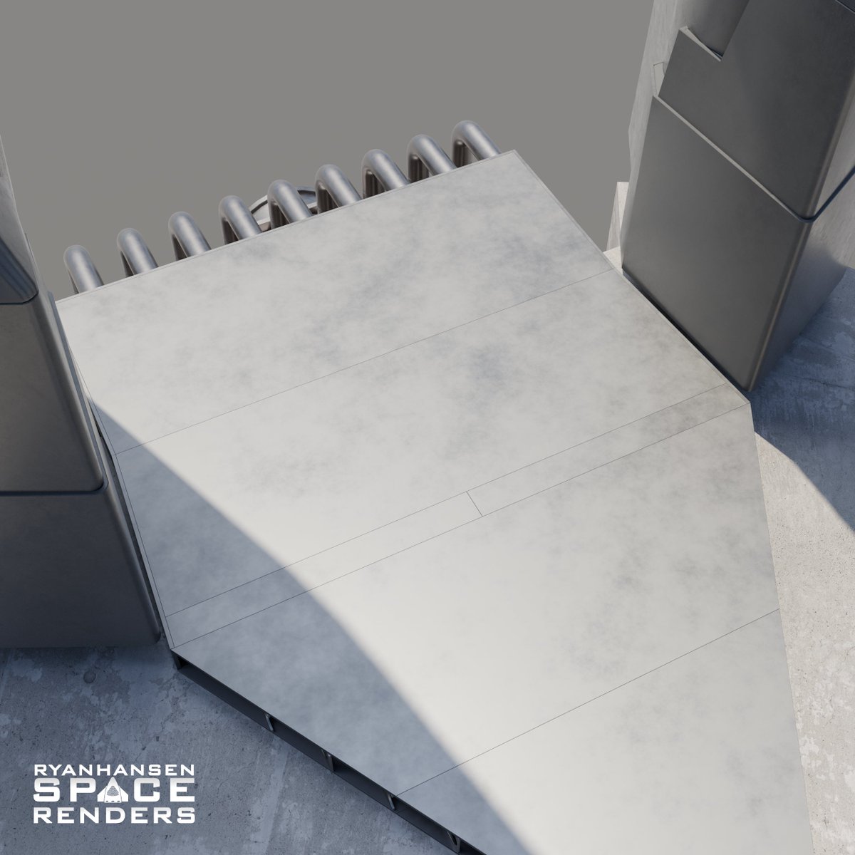
It appears there will be just enough room left on either side of this plate assembly for ease of installation and some smaller steel plates will likely be added to cover the gap between the flame diverters on the legs and the plates. (17/n)
I’ve determined that the plate assemblies appear to be ~0.4m tall OD using a Patreon photo captured by @StarshipGazer. It's unclear if SpaceX will place the plates on top of the original pad height or embed it ~0.4m underground so the top is flush with the original pad. (18/n)
I’m assuming there will be an additional triangular plate that will be welded to the trapezoidal plate to form a large triangular pre-assembly. That means there will be two pre-assemblies that will be built and transported to the launch site separately. (19/n)


Note the small gap between the two pre-assemblies. As of right now, it appears that this will allow SpaceX to weld the two pre-assemblies together in place under the OLM. They may be welded from the inside and then a small plate will be added to the top to finish it out. (20/n)

Assuming there are 6 of each of the pre-assemblies, this is what the steel plates may look like without any of the transpiration holes added. As of right now, it does not appear that any of the transpiration holes exist or they are too small to be seen in any photos. (21/n)

Due to this system being an afterthought, there are some conflicts with the existing infrastructure. One notable item is the concrete encasement for the main propellant lines pictured on the bottom left. (22/n)

A portion of this concrete and the propellant lines have been removed in the last week. Many thought this may be due to damage but I’m speculating that this was always planned so that the water supply line could be routed through here. (23/n)

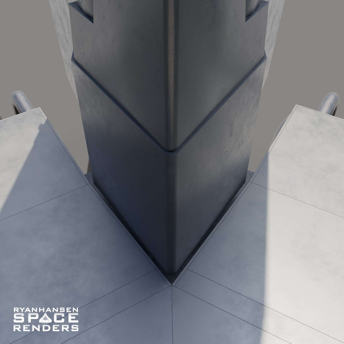
Here is another location with conflicts. This is the side closest to the tower’s north side. This one is going to be more interesting to work around. I have some thoughts on how it could be done but I will wait until I see more indications before sharing anything. (24/n)

Most of the steel used for this system is over 1" (2.54cm) thick. The top plate appears to be ~1.6” (4cm) thick. That thickness is required to deal with several factors. The booster engines will be firing toward the steel producing ~15bar of pressure across the surface. (25/n)
In addition, pressurized gas tubes will be feeding high-pressure gas into water tanks pushing a massive volume of water through the plate system. The water within the plates will likely be somewhere between 20-30bar to overcome the pressure created by the engines. (26/n)
For those that are concerned about the water boiling in the plates, note that the boiling point of water changes based on the pressure it's under. At 20bar the boiling point of water is more than doubled that of 1bar and at 30bar it's around 230°C. (27/n)
Refer back to my previous thread detailing how the water distribution will be used to cool the top of the plate so that the steel itself never reaches a temperature that causes the water to boil before exiting the plate. (28/n)
https://twitter.com/RyanHansenSpace/status/1656448165158027266?s=20
There are many more things I could discuss related to this system but this thread is getting quite long. This transpirational steel plate system will likely go together quite fast so by this time next week there may be even more details visible. (29/n)

If you want to stay up to date on this project make sure to give me a follow! Also, check out the following content creators for more #Starship overviews and discoveries (30/n)
@StarshipGazer
@RGVaerialphotos
@MarcusHouse
@FelixSchlang
@CSI_Starbase
@StarshipGazer
@RGVaerialphotos
@MarcusHouse
@FelixSchlang
@CSI_Starbase
• • •
Missing some Tweet in this thread? You can try to
force a refresh


