SpaceX has made a lot of progress preparing the area around the OLM for the new transpirationally cooled steel plates that will replace the surface below the OLM. I have been observing the changes over the past few weeks and this thread will detail my speculations. 1/n 

Note, I model everything with real dimensions that I calculate from pixel-counting reference images. This method is not always perfect but more times than not it leads to mostly accurate conclusions. With that said, this thread has speculation but it's informed speculation. 2/n
Originally I speculated that there would be 6 water manifolds between each leg under the OLM feeding the “steel sandwich” on each of the 6 sides. This aligns with the design used for the new launch mount at 39A which will use a more mature version of this system. 3/n

To date, only 3 manifolds have been seen being assembled. This implies that only 3 sides of the steel sandwich will feature water inlets. Each manifold is a unique size so I've labeled them “small", "medium", and “large” and will refer to them as such throughout this thread. 4/n

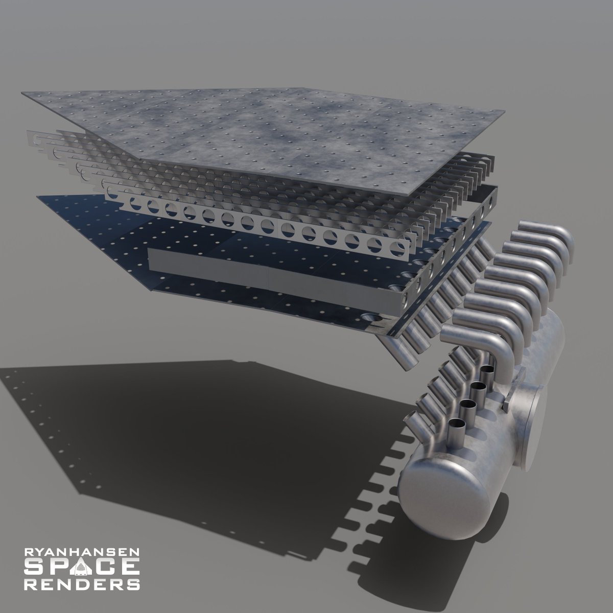
The large manifold has a 5ft inlet with 18 nipples welded to it. There are 9 along the top and 9 along the side. These nipples have tubes welded to them that attach to the steel sandwich's outside edge and bottom. Shielding will be attached to cover the top row of tubes. 5/n
The medium manifold has a 4ft diameter inlet that is angled downwards. It also has 18 nipples placed in a similar manner. These nipples have tubes welded to them and attach to the steel sandwich in the same way as the large manifold and will receive similar shielding. 6/n
The small manifold is a 3ft diameter pipe with a total of 16 nipples attached in various places. Some of the inlet tubes alternate between smaller and larger tubes. All 16 tubes attach to the steel sandwich's outside edge. Shielding on this manifold is a unique shape. 7/n
If there are only 3 manifolds, one would assume that they plan to place each inlet manifold on alternating edges for equal inlet coverage. With that in mind, I started looking at all of the existing underground obstacles that they would need to work around. 8/n

The main obstacles are the prefabricated concrete trenches that house the GSE lines for both the OLM and OLIT. Both of these trenches make it difficult to route a water pipe around to the north side (pictured bottom) of the OLM due to their close proximity to the OLM legs. 9/n

The OLIT trench has a large number of propellant lines and electrical conduits which would be tedious to modify or relocate. For this reason, I think this trench will remain untouched. This older image from @RGVaerialphotos shows the number of pipes in each trench. 10/n

The OLM trench only had a few pipes in it and has since been partially removed. I believe this was planned and is not a reciprocation of any damage caused by the first flight. This trench is by far easier to remove and replace than the previously mentioned OLIT trench. 11/n

Another obstacle to consider is the electrical vaults placed at the base of the north OLM leg. These will likely also not be modified due to the tedious work it would require to relocate and reconnect all the wiring. Recent flyover images also seem to confirm this. 12/n

With those assumptions in mind, I started looking for the 3 sides around the OLM with which manifolds could be placed and routed to. I determined that this side likely will not have a manifold since it seems too difficult to get to given all the constraints. 13/n

After considering the shapes of the manifolds, it became clear that the small manifold would likely be placed on this side since its design seems tailored for the dimensional constraints present, and the elbow welded on the end of the pipe is turned in an ideal direction. 14/n

Before IFT-1, SpaceX installed and buried two pipes behind the tower heading toward the OLM. These pipes were 5ft and 4ft in diameter. Currently, they end in a concrete vault just behind the tower. The other ends have been connected to the water supply tanks. 15/n

One part I have been watching closely is the large Y assembly with a reducer fitting. This reducer changes the diameter of the pipe from 5ft to 3ft on one side of the assembly. Recently, a short 5ft section with a 60° elbow was added hinting where it may go. 16/n

Currently, the small manifold has a 90° elbow attached to it but I believe this will be chopped down to be a 60° elbow much like they have done with other elbows. If that is the case, I assume the 3ft side of the Y assembly will attach to the 3ft pipe of the small manifold. 17/n

This fits ideally for the pipe diameters and it also puts the 60° elbow attached to the Y assembly directly in line with the 5ft pipe coming from the water tank area. It also makes sense to place the Y assembly on this side of the OLM decreasing the number of elbows. 18/n

The large manifold has a 5ft pipe so it must be connected to the last open side of the Y assembly. Coincidently enough, it appears that if the manifold is placed along this edge it is directly in line with the Y assembly. Only requiring a small section of pipe added to it. 19/n

Placing the large and small manifolds on these alternating edges lines up with the assumption that every other edge will have an inlet manifold. That leaves one edge open on the north side of OLM for the medium manifold to be placed. 20/n

Assuming that the medium manifold goes in this location, the downward angle of the inlet makes sense. This manifold will need to be routed around the OLM trench and this downward angle coupled with a 90° elbow allows the 4ft inlet pipe to be routed under the OLM trench. 21/n

If the inlet pipe does not go under the trench then the trench will need to be relocated further from the OLM to allow the water pipe to fit between the leg and the trench. This would also require a new longer “doghouse” to be used and that could lead to issues. 22/n

If the water pipe is routed under the GSE trench then SpaceX could rebuild the same trench after the pipe is put into position and reuse the same “doghouse”, which protects the propellant lines as they come out of the ground, which was kept after it was removed. 23/n

As previously mentioned, the second pipe in the vault behind the tower is 4ft in diameter so it makes sense that this pipe would be routed under the 5ft pipe and then around the OLM to be connected to the medium manifold since it’s inlet is a 4ft diameter pipe. 24/n

With the 3 remaining non-fed manifolds put in place and all the pipe routing complete, this is what the full system may look like. It is possible that some smaller auxiliary water lines are added for additional cooling but I will have to wait and see if any are installed. 25/n

SpaceX has begun installing the rebar for the pile cap that will sit on top of all the piles that were drilled. I have not been able to map all the smaller piles but I was able to find a majority of them. This is what all the piles and pile cap may look like once finished. 26/n

This is getting further into speculation territory but I’m suspecting they may make some walls around the inlet manifolds to provide an open area. This would aid with any maintenance down the road or even replacement as this system seems designed to allow that. 27/n

This could allow SpaceX to fill around the pipes with dirt/sand and then cover the top with a layer of concrete creating the work surface around the OLM. It's too soon to tell if this is actually what they plan to do but the amount of excavation they’ve done gives hints. 28/n

As of now, this is my best guess of how all this goes together. As more parts get finalized it will become more clear. While putting this together I already noticed some small refinements that I may need to do based on the available parts. 29/n

This “water deluge” system sure is unique. I’m very curious to see how all the parts and systems end up working in the end around the moment of ignition. I predict they will test it by itself and again with multiple B9 static fires. What do you think of this system? 30/n
Thanks to @RGVaerialphotos for providing excellent reference images with his flyovers. Throughout this process, I camera-matched MANY of his images to help aid with this design. This is what my speculation of the system looks like overlayed with one of his camera-matched images.

• • •
Missing some Tweet in this thread? You can try to
force a refresh