Since my last thread, #SpaceX has made a lot of progress with the upgrades beneath the #Starship OLM. In this thread, I will give an updated look at the transpirationally cooled steel plates and explain how they will all come together as well as some additional speculation. 1/n 

If you haven’t seen my previous thread I HIGHLY recommend checking it out first. It has a lot of details that I either won’t mention here or will expand on or correct and it might be confusing without any context. 2/n
https://twitter.com/RyanHansenSpace/status/1670501687696523264?s=20
Shortly after the first of the year, SpaceX began building different sub-sections. It was clear there would be several different shapes consisting of rectangles, trapezoids, and recently revealed, hexagons. Several different configurations of some shapes were also used. 3/n

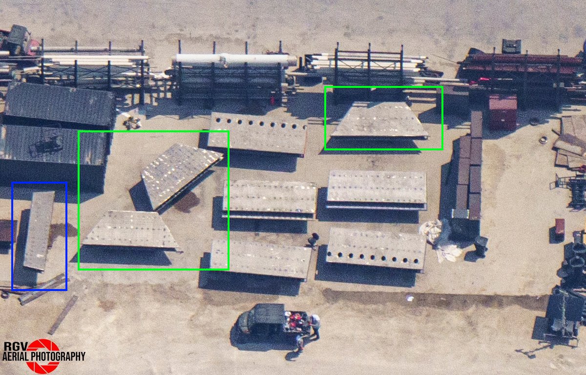
In this image by @RGVaerialphotos, we can actually see all of the parts that would eventually make up 3 of the 6 assemblies that go between the OLM legs. In this case, they also happen to be the 3 manifold assemblies mentioned in the previous thread. 4/n

Several sections disappeared and were presumed to be inside the inventory tent. I assumed the 3 larger trapezoid sections would be part of the center assembly but I was unsure about this smaller trapezoid on the left. Measuring these parts gave some hints. More on that later. 5/n
In the previous thread, I touched on the design of the 3 known manifold assemblies. At the time we hadn't seen the center section yet so I chose to include parts in those animations that would likely be part of the center assembly to make it clear there would be more parts. 6/n

While working on my previous thread, I was skeptical about the completeness of the small manifold. After publishing, I decided that the small manifold was going to be slightly different than the other manifold assemblies because it was missing a large part the others had. 7/n

Let's go over each of the known assemblies now that we have more information. I was able to spy accurate measurements marked on the sides of the assemblies during rollout so I decided to remodel everything from scratch. Now I am more confident in my measurements. 8/n
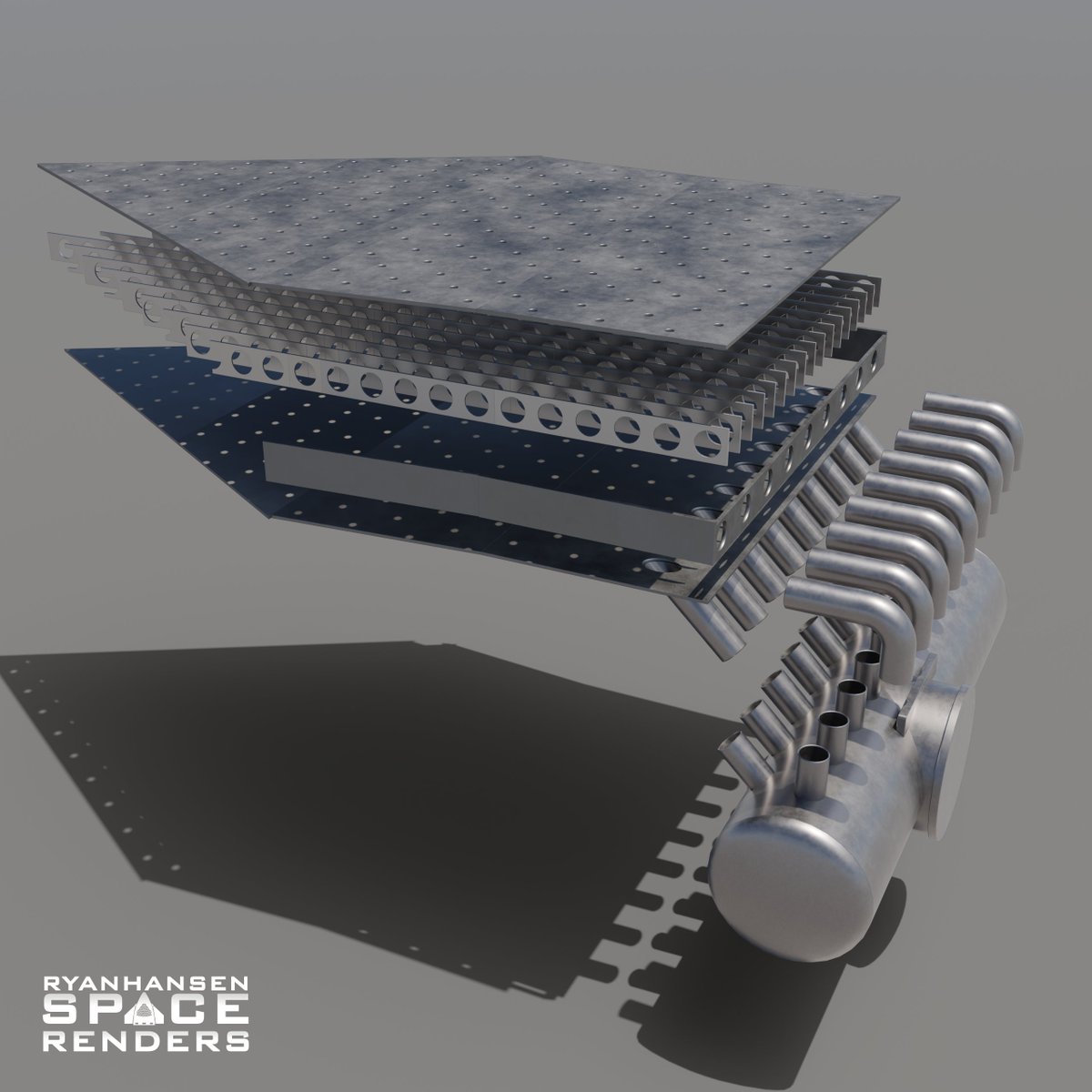
The large manifold section consists of a rectangular section connected to a slightly trapezoidal section. Both of these sections feature 17 vertical supports that create 18 channels internally. The top plate on the trapezoid section is cut short. More on that later. 9/n
The medium manifold section is similar to the large manifold section. Both have the same shapes and top plate cut short with 18 channels internally. The main difference is there are 26 tubes connecting this section to the inlet pipe instead of 18, as previously thought. 10/n
The small manifold consists of a single rectangular section that is narrower than the other sections. For this reason, it has 16 tubes feeding it but still has 17 vertical supports making 18 channels. The top rectangular plate is cut short similar to the other manifolds. 11/n
The center assembly is comprised of a hexagonal section surrounded by 6 large trapezoidal sections, 3 of which seen previously. To decrease the number of separate assemblies SpaceX also attached 4 small trapezoids to this assembly that will sit between some of the OLM legs. 12/n
One of the 4 outer trapezoid sections has a machined plate with square holes inset into it. The other 3 trapezoids have 10 capped holes, which are a bit puzzling but more on that later. The remaining 2 sides of the center assembly are wide open without any plates or caps. 13/n

Before concrete was poured, large 2in thick embeds were placed so that they would sit above the concrete surface. The holes allow concrete to fill under the plates. These will provide a flat metal surface for the steel assembles to be welded to once lowered into position. 14/n

I was right about the locations for 2/3 of the manifolds. The large and small manifolds appear to go where I speculated, but the medium manifold will go between them. This does make a lot of sense when considering the propellant trench constraint. 15/n

I was expecting to see a cutout in the rebar for the medium manifold since the inlet pipe angles downward. That cutout was visible, just not where I originally thought it would be. The final layout of the rebar also indicated all 3 manifolds would be on one side of the OLM. 16/n

Since we know the locations of the 3 manifolds, the orientation of the center section can be determined. The trapezoid with the square holes will attach to the small manifold and the open hexagonal edges without any trapezoids will connect to the medium and large manifolds. 17/n

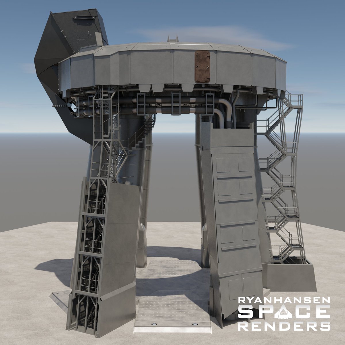
The center section will be installed first. Due to its size, it cannot be lowered through the top of the OLM. It must be transported between the legs at an angle and then picked up and oriented into position by a pair of cranes. This has been completed. 18/n
Once the center is in place, each manifold assembly will be lowered into place next to it. This will require moving the center of mass with beams and possibly weights so a crane can connect to a point on the assembly that does not have part of the OLM directly above it. 19/n
Once the manifold sections are lowered into place, they will be welded to the center section to create one assembly. Workers will need to access all of the edges, including the bottom, for welding but they cannot reach it from below with everything sitting on the concrete. 20/n

This is likely why the manifold assemblies have the top plate cut short. Workers will weld the bottom plate from the top side adding any additional plates for the channels before adding the top plate to finish the sealing process. This will require many weld passes. 21/n
The 3 exposed embeds on the sides with the capped holes indicate there may be additional sections placed here. Rectangular steel sections are being built at the launch site but it's unclear how they will work with the capped holes. They are also different steel thicknesses. 22/n

This is what I think the final system may look like. The holes are too small to be seen in any photos (exaggerated here) but there is evidence of them. At this time I believe we will see more of a mist than jets of water but after the first test will we will know for sure. 23/n

It appears that the new concrete footing sits flush with the original pad height. This means the blast surface will be ~18in closer to the engines with the new steel plates. A ramp will need to be built to allow work platforms to be moved under the OLM. 24/n

This is what I currently suspect the supply pipe routing could look like given the remaining pipes at the launch site. This appears like it will be a slower cut-to-fit process accounting for any slop due to construction tolerance errors. 25/n

At the time of writing this, SpaceX is staging the 3 manifold sections near the OLM for installation and the removal of dirt for the supply pipes has started. It won’t be long before the large pipes are lifted into position and cut to fit. 26/n
There are still a few mysteries left to uncover regarding this system. I will continue to watch as parts take shape and get near their intended places and update my models. In a few weeks, we should see the first test of the transpirational steel plate. 27/n
This may be my final thread on this topic unless something special starts to take shape. I will still showcase renders of this system from time to time but I will leave the really detailed deep dives to @CSI_Starbase since videos are a better medium for content like this. 28/n
• • •
Missing some Tweet in this thread? You can try to
force a refresh