Ryan Hansen Space Profile picture
Mar 9 20 tweets 7 min read Read on X
Shortly before I posted my first detailed thread about my #SuperHeavy #B9 propellant simulation results, #SpaceX rolled B10 to the launch site, and some new weld marks were observed in the lower LOX tank. Like others, I also speculated this may indicate new slosh baffles. /1 Image
It appears SpaceX determined the existing baffles within the LOX tank aren’t enough to mitigate slosh at staging. Using the weld marks, I devised a few designs and tested them with the same conditions as the previous thread to see how each design would change the liquid behavior. /2
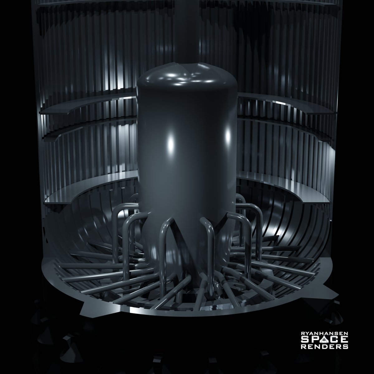
Before looking at any new simulations, let's look at the original side cutaway. I will be using this angle and animation throughout this thread to make comparisons. Also, keep in mind my disclaimer in the previous thread about these results and their theoretical accuracy. /3
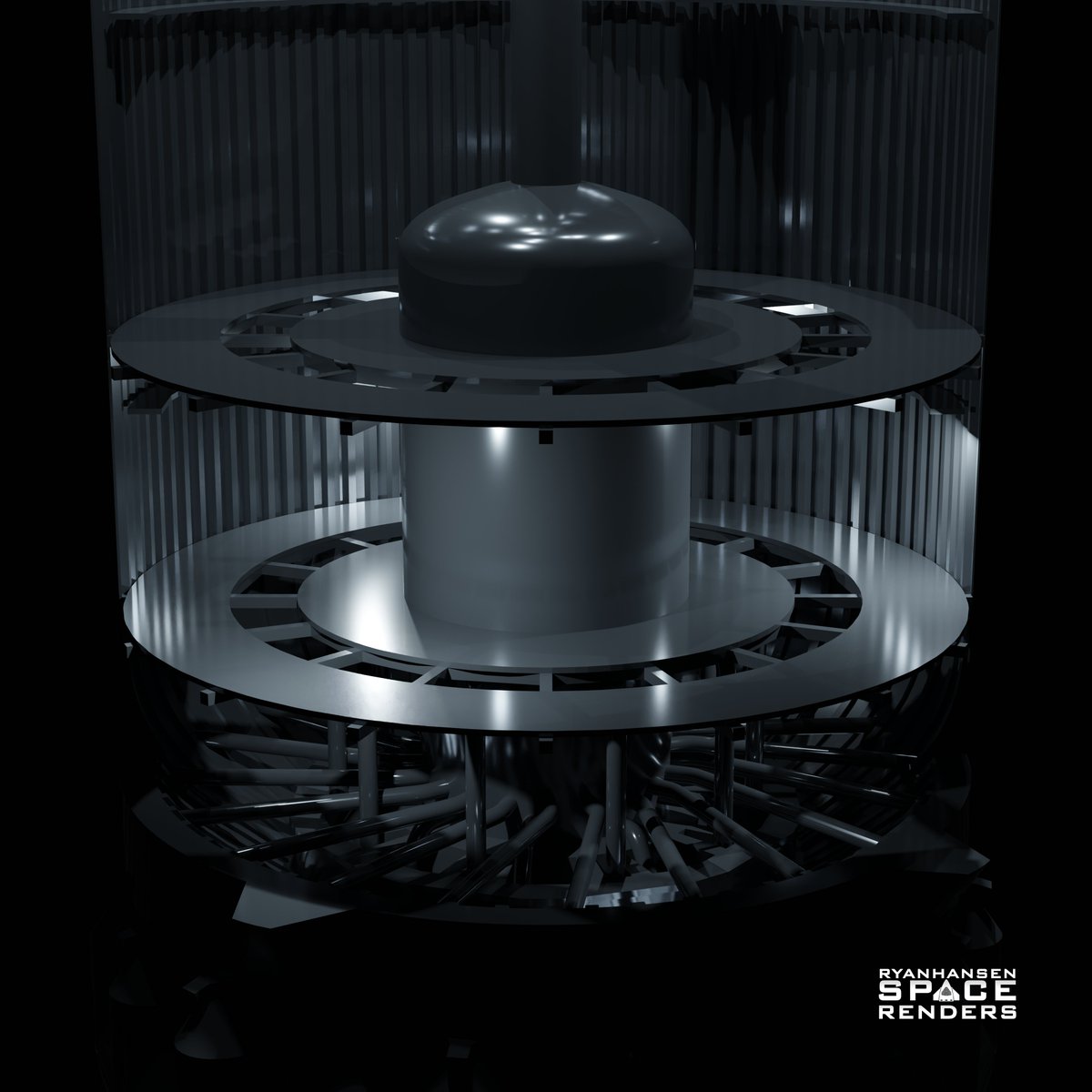
The first design is two large ring baffles similar to the existing baffles but they extend further out from the tank walls. The thought is these baffles could catch more of the liquid as it is accelerated upwards and divert it inwards to choke additional upward liquid motion. /4 Image
You can see from the results these baffles do very little to prevent the upward motion of the liquid. A pretty strong column of liquid in the middle is thrown upwards still. When that column of liquid crashes down it exerts unwanted forces and introduces trapped gas bubbles. /5
The second design is like the first but I’m including a larger ring baffle around the LOX landing tank. There is no proof this exists but it should provide some resistance to the liquid column that moves upwards in the center observed in the previous simulations. /6 Image
Unfortunately, that doesn't help much. It seems that reducing the cross-sectional area while leaving a large opening just funnels the liquid into the gap producing a “finger over the hose” effect. This obviously will not help the situation of preventing slosh. /7
At this point, I considered taking the second design and increasing the baffle size again extending them further toward the middle of the tank. This comes with its challenges since the propellant mass will now exert more torque on the baffle the further it extends. /8
As the baffle size increases, supporting the baffle with only the exterior wall becomes more challenging or impossible. Cross-bracing would eventually be needed to span between the exterior walls and the landing tank so that larger surfaces could be properly supported. /9 Image
While that design might work, I decided to skip ahead to a design that I felt had a better chance of showing improvement. Each simulation takes around a week to simulate and render so I didn't want to waste time on a design that might not yield any visual improvement. /10
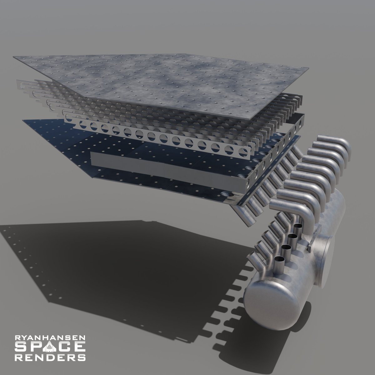
The third design is intended to act like an industrial flow restrictor. These are essentially 9m wide plates with orifices that restrict fluid motion. The quantity and size of the orifices would be determined by the flow rate needed for all 33 engines on ascent. /11 Image
As I hoped, this design has a noticeable improvement and keeps more liquid at the base of the tank where the engine inlets are. However, I’m not sure how realistic this design is as it would have mass penalties and possibly unwanted fluid dynamics in its depicted form. /12
In this comparison, you can see how much cleaner the liquid is without all the propellant crashing down causing gas bubbles to be trapped under the surface. This would ensure more laminar flow into the engine inlets as well. /13
From all my testing, the most effective solution involves a structure covering the complete cross-section of the tank while still letting enough propellant through passively to not restrict flow while all 33 Raptor engines are burning through the ascent portion of the flight. If SpaceX has implemented something like this inside B10 it likely looks a bit different. /14
SpaceX has implemented many changes to B10 and S28 to try and prevent the failures from the last flight. I believe the configuration for IFT-2 was possibly a worst-case scenario for data collection and IFT-3 will feature many changes based on that data. I’m guessing staging will be softer due to reconfiguring the engine parameters around hot staging. I don’t know what exactly, but they may play with the engine counts and ignition timing to reduce the deceleration on the booster. /15
With that in mind, I wanted to see what it would look like if SpaceX could reduce the deceleration on the booster during hot staging by half. I don’t know if this is realistic in practice, but changes in acceleration will have a large impact on the simulation. /16
As you can see, reducing the deceleration significantly changed the liquid behavior. This isn’t to say that they can reduce the declaration this much, but more to show a combination of changes can have a big impact on giving B10 the best chance at a powered landing in the gulf. /17
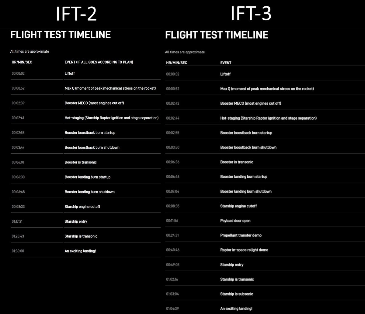
Another thing to note in the previous simulation is how the liquid sloshes to one side during the booster rotation. I'm wondering if this is the reason why the boostback burn is beginning 1 second earlier in the IFT-3 timeline. This could be intended to pull the liquid more evenly to the bottom of the tank before rotating the booster. /18Image
I think SpaceX learned a lot from IFT-2 data and the additional weld marks on B10 indicate some level of slosh they would like to mitigate. I’d like to think that they implemented something like my last design but we won’t know unless SpaceX tells us. /19
Taking into consideration the possible changes covered in this thread and assuming some other unforeseen issue doesn’t pop up on ascent, I think B10 has a good chance of making it through the boostback burn during IFT-3. Excitement guaranteed! /20

• • •

Missing some Tweet in this thread? You can try to force a refresh
 

Keep Current with Ryan Hansen Space

Ryan Hansen Space Profile picture

Stay in touch and get notified when new unrolls are available from this author!

Read all threads

This Thread may be Removed Anytime!

PDF

Twitter may remove this content at anytime! Save it as PDF for later use!

Try unrolling a thread yourself!

how to unroll video
  1. Follow @ThreadReaderApp to mention us!

  2. From a Twitter thread mention us with a keyword "unroll"
@threadreaderapp unroll

Practice here first or read more on our help page!

More from @RyanHansenSpace

Feb 20
Interesting parts are taking shape at #SpaceX's Masseys test site. As more work is completed on the new flame diverter, seemingly random parts start developing into recognizable assemblies. In this short thread, I'll present some ideas surrounding these new parts. As always, this is speculative and subject to change. /1Image
As always, I do my best to model in detail with accurate measurements from recreated camera shots. Here are my models with one of the images I used from @RGVaerialphotos's recent flyover. Consider becoming a flight supporter as things get more interesting at the Masseys site. /2 Image
First up is the assumed "flame bucket" part of the diverter system. This will be built using 4 pedestals with 6 slots allowing the 6 "C" shaped beams to be attached to form the frame for a curved surface with walls. /3 Image
Read 7 tweets
Feb 14
It's finally time to unveil my #SuperHeavy #B9 propellant simulation results! In this thread, I will
include some animations with data and provide some brief details about the process. I may make another thread explaining this process in more detail at a later date if desired. /1 Image
I started this project the day after #Starship IFT-2 with some basic tests. It took nearly a month to go from a conceptual idea to a workflow that seemed like it could work and produce fairly accurate results with the limited data that onlookers have access to. /2
Simply put, the plan was to recreate the flight path and match the tracking camera angles. Then animate my models to match the motion of B9 and then use that animation data to calculate the 3-axis acceleration of B9 for every frame. Then I could use that acceleration data to drive forces within a fluid simulation. /3
Read 21 tweets
Jul 7, 2023
Since my last thread, #SpaceX has made a lot of progress with the upgrades beneath the #Starship OLM. In this thread, I will give an updated look at the transpirationally cooled steel plates and explain how they will all come together as well as some additional speculation. 1/n
If you haven’t seen my previous thread I HIGHLY recommend checking it out first. It has a lot of details that I either won’t mention here or will expand on or correct and it might be confusing without any context. 2/n
Shortly after the first of the year, SpaceX began building different sub-sections. It was clear there would be several different shapes consisting of rectangles, trapezoids, and recently revealed, hexagons. Several different configurations of some shapes were also used. 3/n
Read 28 tweets
Jun 18, 2023
SpaceX has made a lot of progress preparing the area around the OLM for the new transpirationally cooled steel plates that will replace the surface below the OLM. I have been observing the changes over the past few weeks and this thread will detail my speculations. 1/n Image
Note, I model everything with real dimensions that I calculate from pixel-counting reference images. This method is not always perfect but more times than not it leads to mostly accurate conclusions. With that said, this thread has speculation but it's informed speculation. 2/n
Originally I speculated that there would be 6 water manifolds between each leg under the OLM feeding the “steel sandwich” on each of the 6 sides. This aligns with the design used for the new launch mount at 39A which will use a more mature version of this system. 3/n Image
Read 31 tweets
May 18, 2023
#SpaceX has started making some progress on the transpirational steel plate system that will be installed under the #Starbase #Starship OLM. In this thread, I will be detailing the latest findings as well as touching on my process for reverse engineering a system like this. (1/n) Image
I completely redid all my models related to this system. The supply pipes and manifolds have been measured and accurately modeled. I was able to gather enough reference photos to get many of the dimensions for the plates and have sized those accordingly. (2/n) Image
A few weeks ago, @RGVaerialphotos captured this photo. At the time, I noticed some of the rectangular plates appeared to have a very slight slant to them. (3/n) Image
Read 30 tweets
May 10, 2023
There have been many questions and concerns about the water-cooled steel plate that is planned to be installed under the OLM. I’ll go over some details about it in this thread and maybe ease some of the concerns. There will be some speculation in this towards the end. (1/n) Image
The term “water-cooled plate” is a bit misleading for people who don’t understand how the system will function. Many may relate this system to a closed-loop water loop used on some high-end gaming computers or the liquid intercooler system used in high-performance vehicles. (2/n)
While water will run through the plates, the main cooling effect comes from holes that will “leak” water onto the surface of the steel. This is required as it cools the metal surface and absorbs energy from the plume at the same time. There are other advantages as well. (3/n) Image
Read 14 tweets

Did Thread Reader help you today?

Support us! We are indie developers!


This site is made by just two indie developers on a laptop doing marketing, support and development! Read more about the story.

Become a Premium Member ($3/month or $30/year) and get exclusive features!

Become Premium

Don't want to be a Premium member but still want to support us?

Make a small donation by buying us coffee ($5) or help with server cost ($10)

Donate via Paypal

Or Donate anonymously using crypto!

Ethereum

0xfe58350B80634f60Fa6Dc149a72b4DFbc17D341E copy

Bitcoin

3ATGMxNzCUFzxpMCHL5sWSt4DVtS8UqXpi copy

Thank you for your support!

Follow Us!

:(