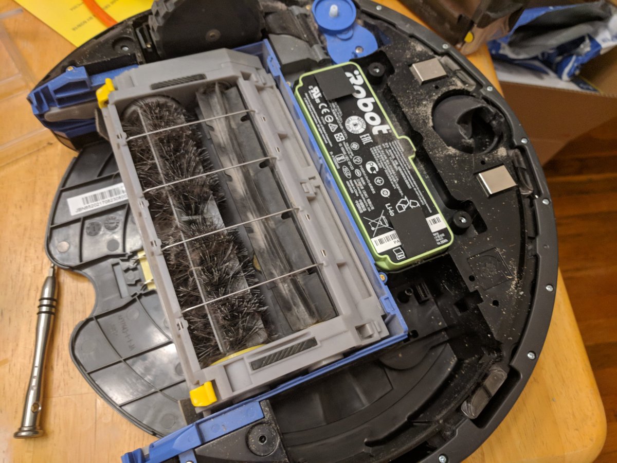
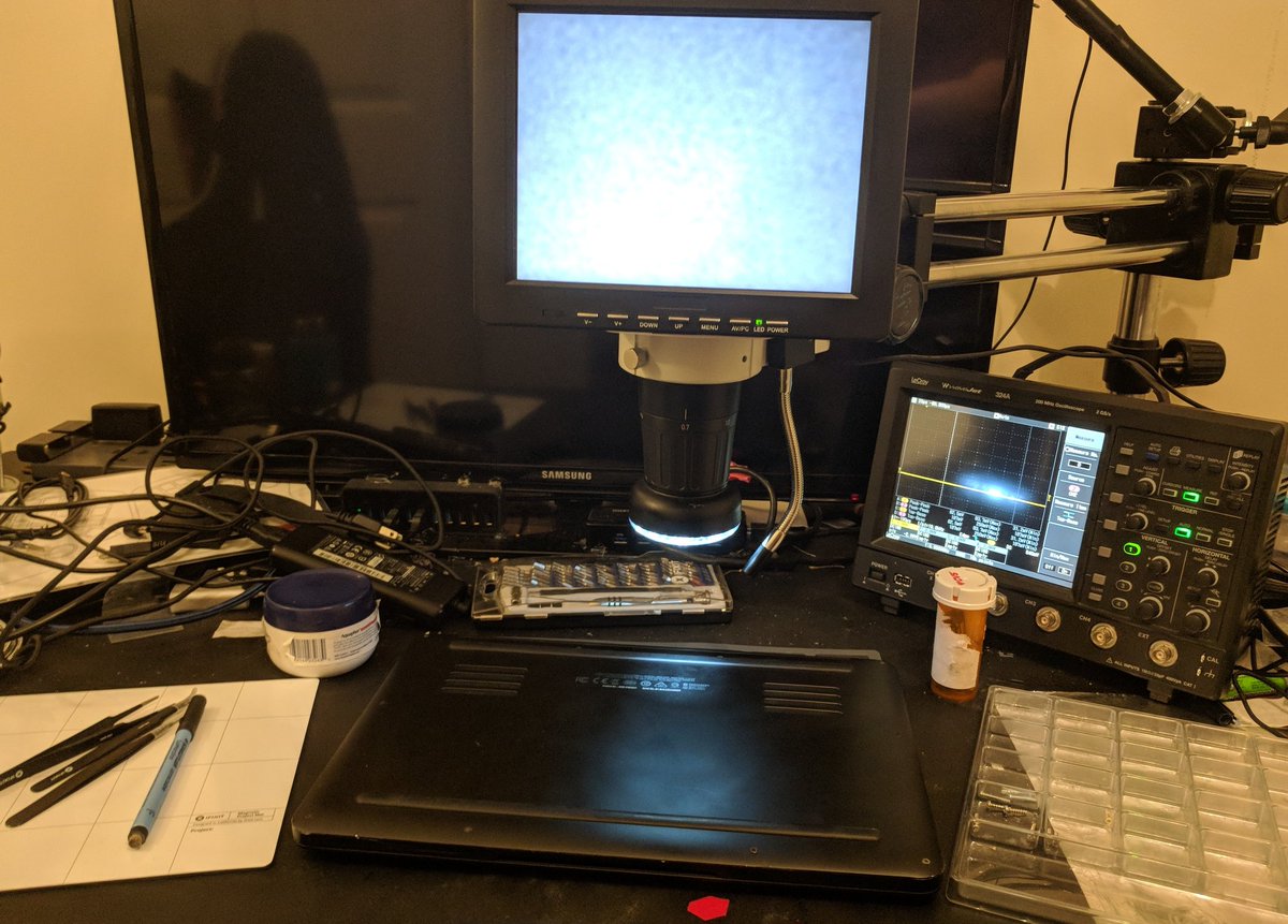
Part one, teardown.
Part two, diagnose(?)
Part three, repair(???)
Part two, diagnose(?)
Part three, repair(???)

Where the fuck is my groundstrap???

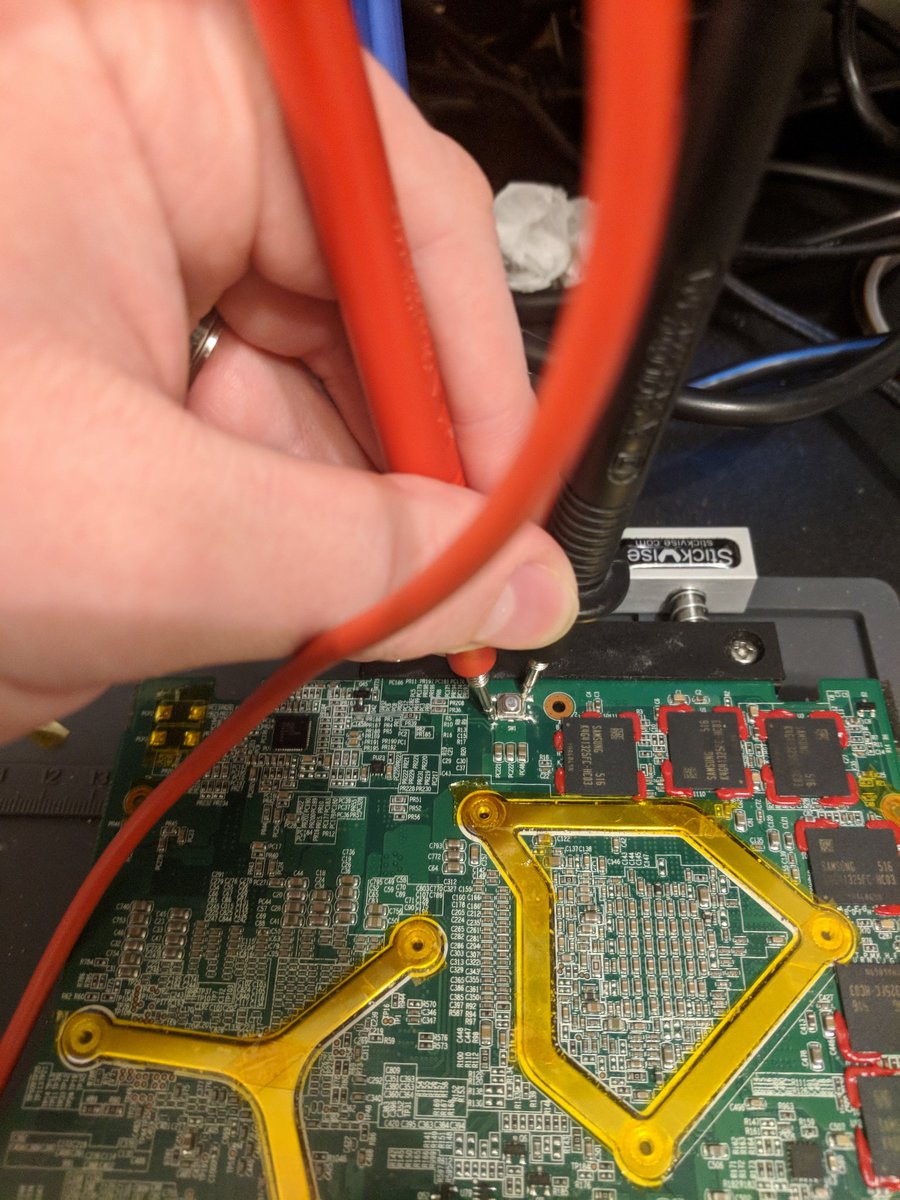
Inside of laptop, back side of motherboard, cables disconnected

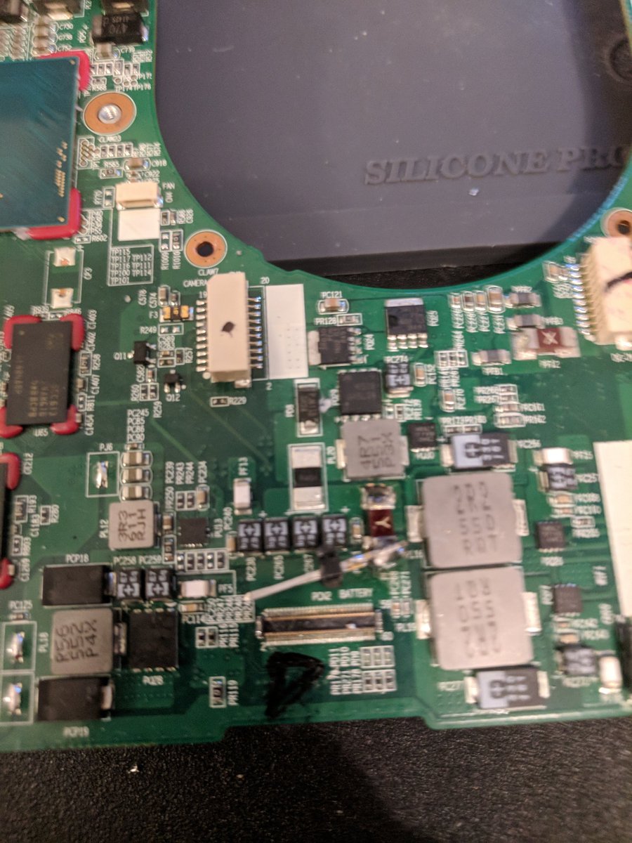
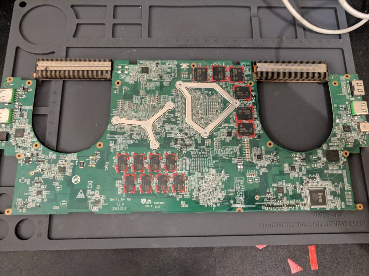
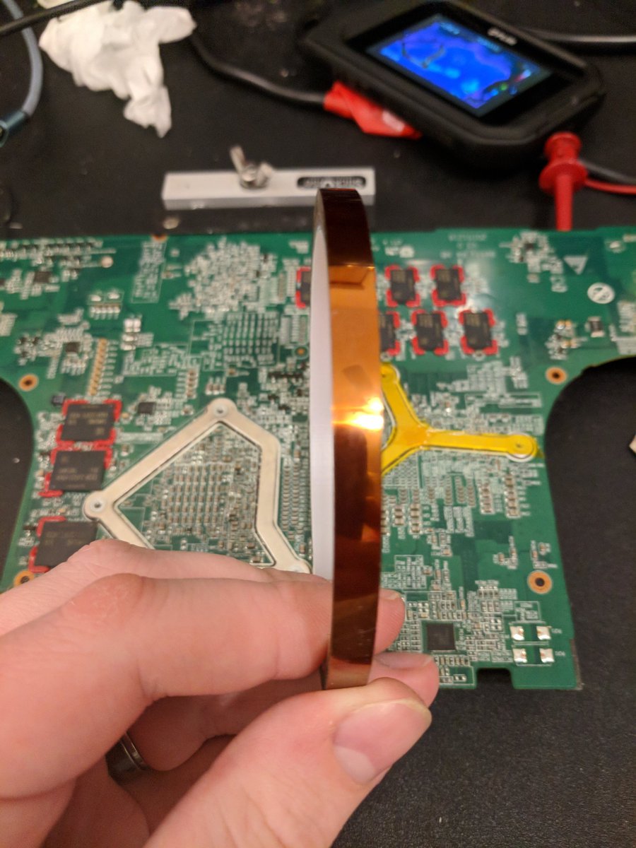
Front and back of mobo. During my testing earlier, p sure I noticed that the MCU responsible for power button management is under the heatsink, so might as well get that off while we're at it.
Also I found my ground strap!
Also I found my ground strap!


So, after a bunch of investigation, it looks like I've mostly pinned down the issue: the power frontend seems fucked, as these power mosfets are not being switched or even driven, and they provide power to the rest of the board.


I'm about 70-ish% sure the issue is this guy, the Intersil 95520HRZ, which should be responsible for load balancing between the battery and the DC supply by controlling those 2 FETs.
No AC or DC at gate, 20V at drain, gotta think it's not doing it's job.
No AC or DC at gate, 20V at drain, gotta think it's not doing it's job.


Ok, now it's time for me to go to sleep, I will probably test my theory by playing with /very very very/ carefully bypassing that IC and the FETs tomorrow to see if I can get the board talking. Night all!
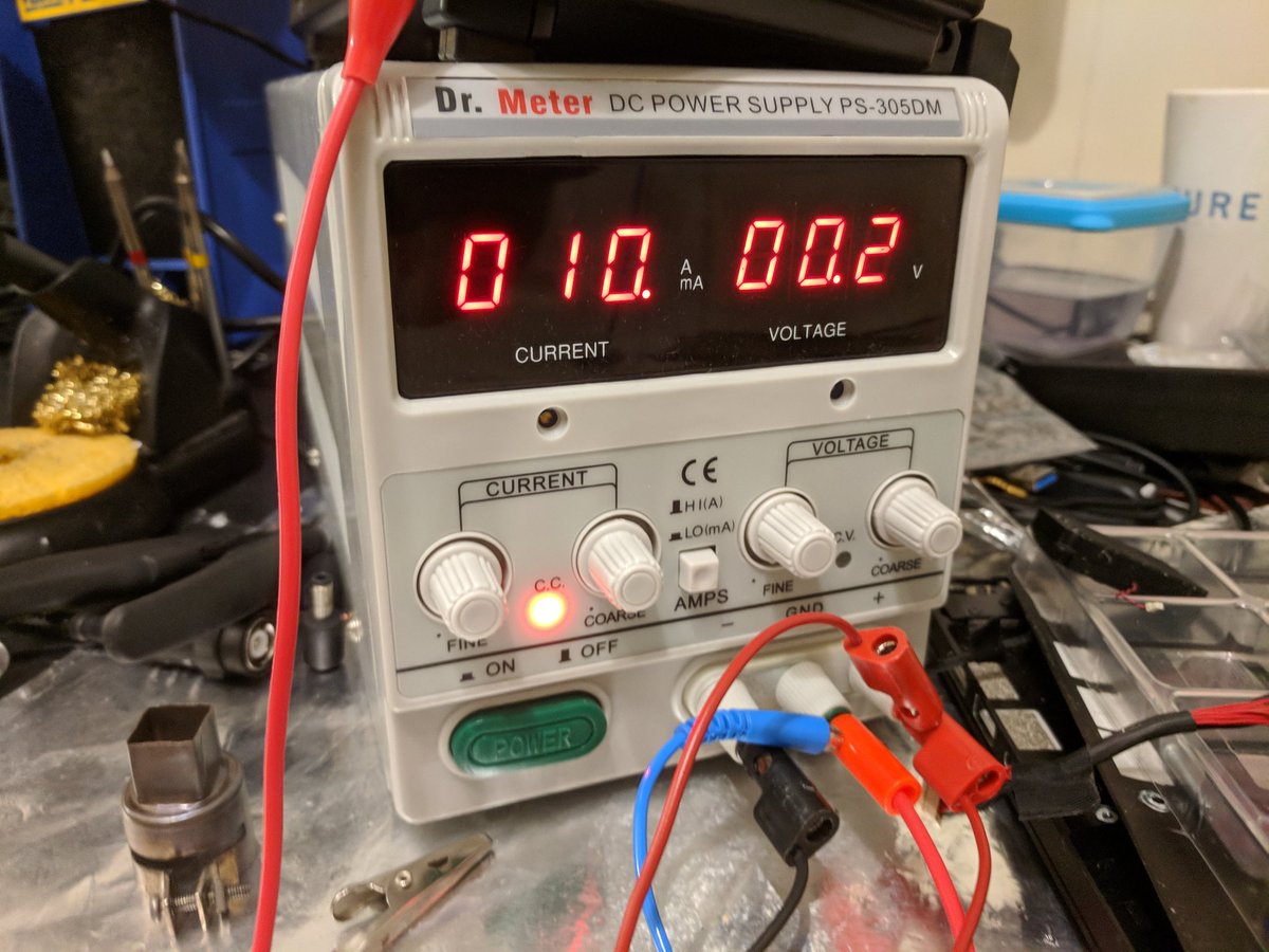
So, been working on this for the last 4 hours now, mostly just trying to verify last night's conclusions. Replaced the laptop supply with my DC supply so I could gauge current into the board and prevent any over-current. Latent power draw is 2 mA when hooked up to DC. Seems right

Basically, the question is will it draw a reasonable amount of current if I short those 2 transistors, so I'm going to apply a 10 mA or so limit, and it shouldn't spike the quiescent current when there's no battery. Wish me luck!
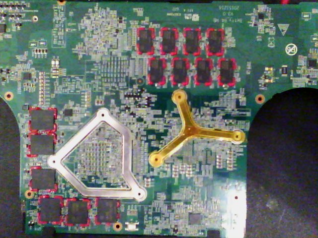
Current definitely spiked up, so now I'm going to do a bit of an experiment instead: I'm going to try to reverse the circuit a little bit to figure out what the intended voltage is. Here's pics of front and back of board. Not exactly clean.


First bit of reversing done, couldnt find datasheets for half the components but thats ok. I think the inductor is what power for the battery charging path is driven through, and I think that diode is backwards. I'm going to translate this to a proper circuit. afaict A = main Vcc


So, I think this is mostly right, but I haven't seen this converter layout before... It doesn't look like a buck converter or a flyback or a boost.... I need to figure out where this inductor goes... and check the direction of this diode...

It kinda looks like buck-boost? but the inductor is before the transistor... This is weird or I'm being stupid. Any input appreciated.
Bad news: Well, I tried bypassing the power supply, and it appears the issue is somewhere downstream :/
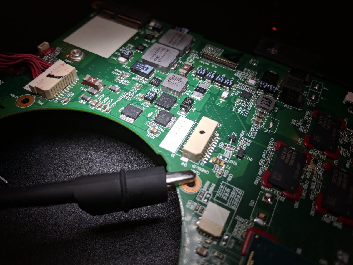
Good news: the motherboard designers planned for this, theres a bunch of jumper isolation points that are just solder blobs, with the 2 pictured being 0 ohms to main supply
Good news: the motherboard designers planned for this, theres a bunch of jumper isolation points that are just solder blobs, with the 2 pictured being 0 ohms to main supply

Plan: break these, test impedance from supply to ground. Currently the quiescent steady state impedance registered by my meter is 15 ohms or so. If I'm lucky, splitting one of these off will change that. Next option is removing the smd fuses for the same purpose.
God I fucking hate silver-based solder so much look at how bad this desoldering is

There we go, got through both, and it worked. Main supply rail is no longer pseudo-shorted to ground. Going to test to see if board holds power now. Seems the issue is on the main CPU supply which... Sucks, but it does shrink the test surface. Also fuck non-lead solder so much

Nope, still can't supply power without drawing >10 mA, which is entirely too high. It's not just caps charging, >10 mA of quiescent current would drain the battery in a couple of days tbh. Quiescent draw at 2 V applied to battery socket should probably draw 2 mA max.
So, now that impedance is reasonable? Move to next step. I'm going to work on removing fuses point-by-point and working my way from the battery to the faulty location. That or throw it on the preheat plate and de-join every single jumper point. One or both of those 2.
Either way though that's for tomorrow, for today I'm going to sleep. Night all, see you in the morning or whenever!
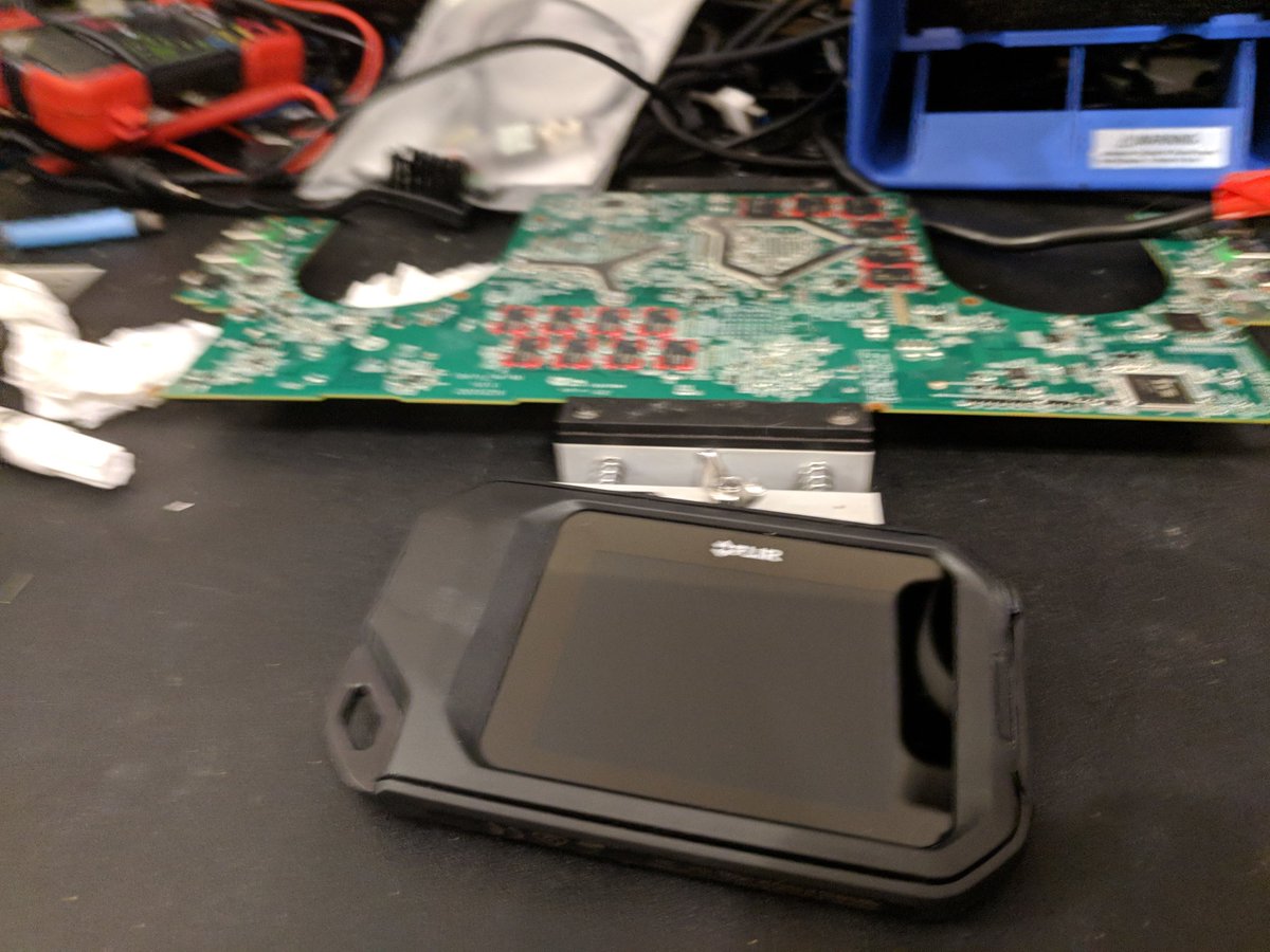
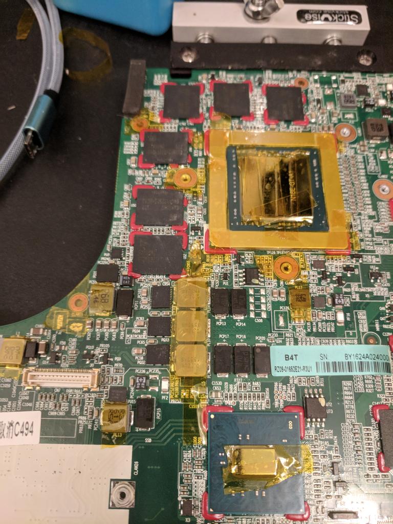
So, because I realized this is going to be a lengthier (and much more frustrating) process than originally thought, I'm making some changes to the workflow. First off, went ahead and cleaned off the thermal paste and transferred the component putty back to the heatsink


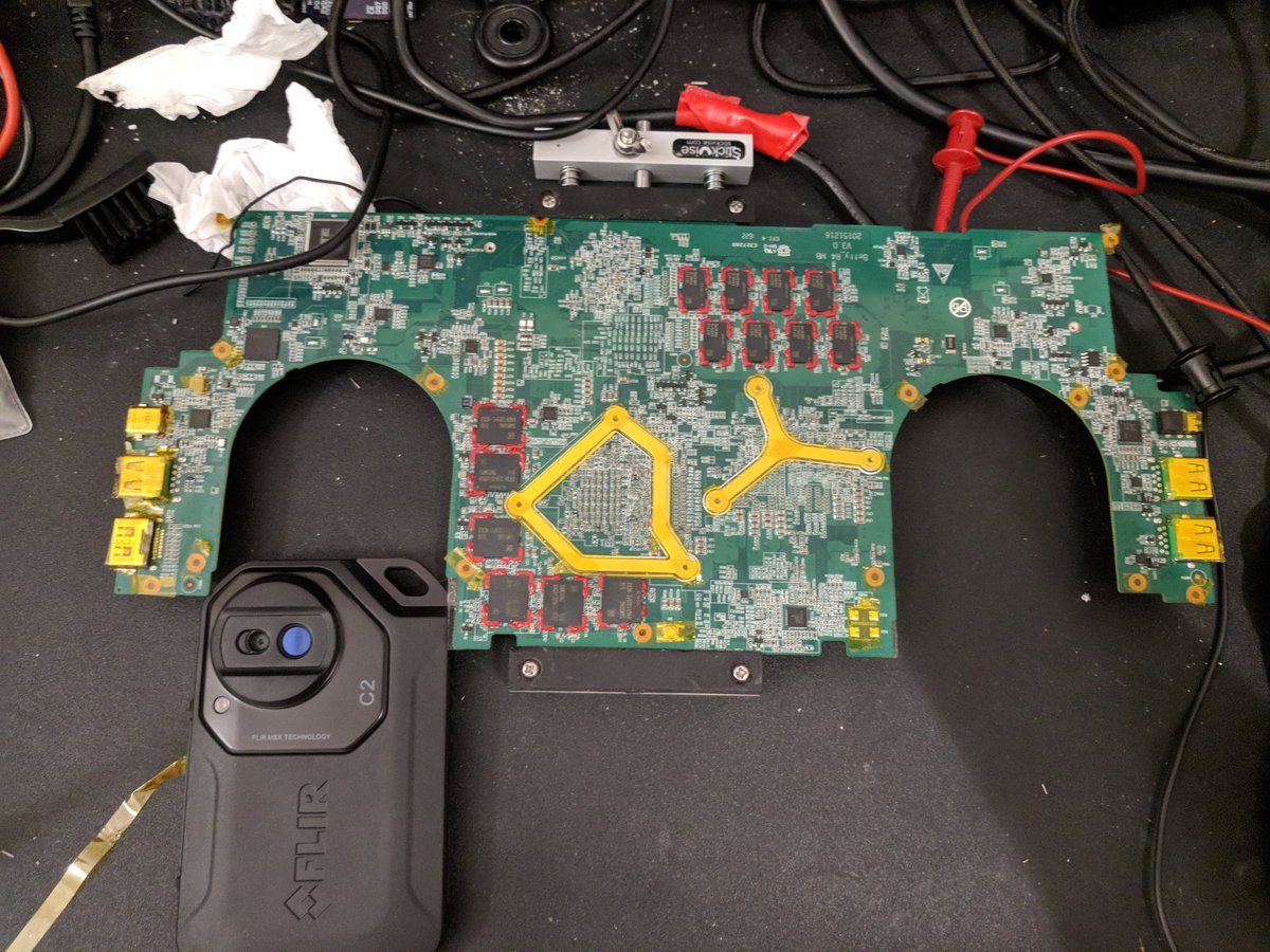
Second, went ahead and bought a FLIR C2 (sorry @cybergibbons i had to, plus it sounds fun to replicate the bug) to help with locating the short, since there's just too many devices to test manually if my initial debugging doesn't work. Should make locating burnt IC's way faster!

The next thing I'm going to do after I get some chores done is add a more permanent point for supplying an external voltage right here since tapping it with probes is risky and not super effective. This is all to facilitate a better test workflow.
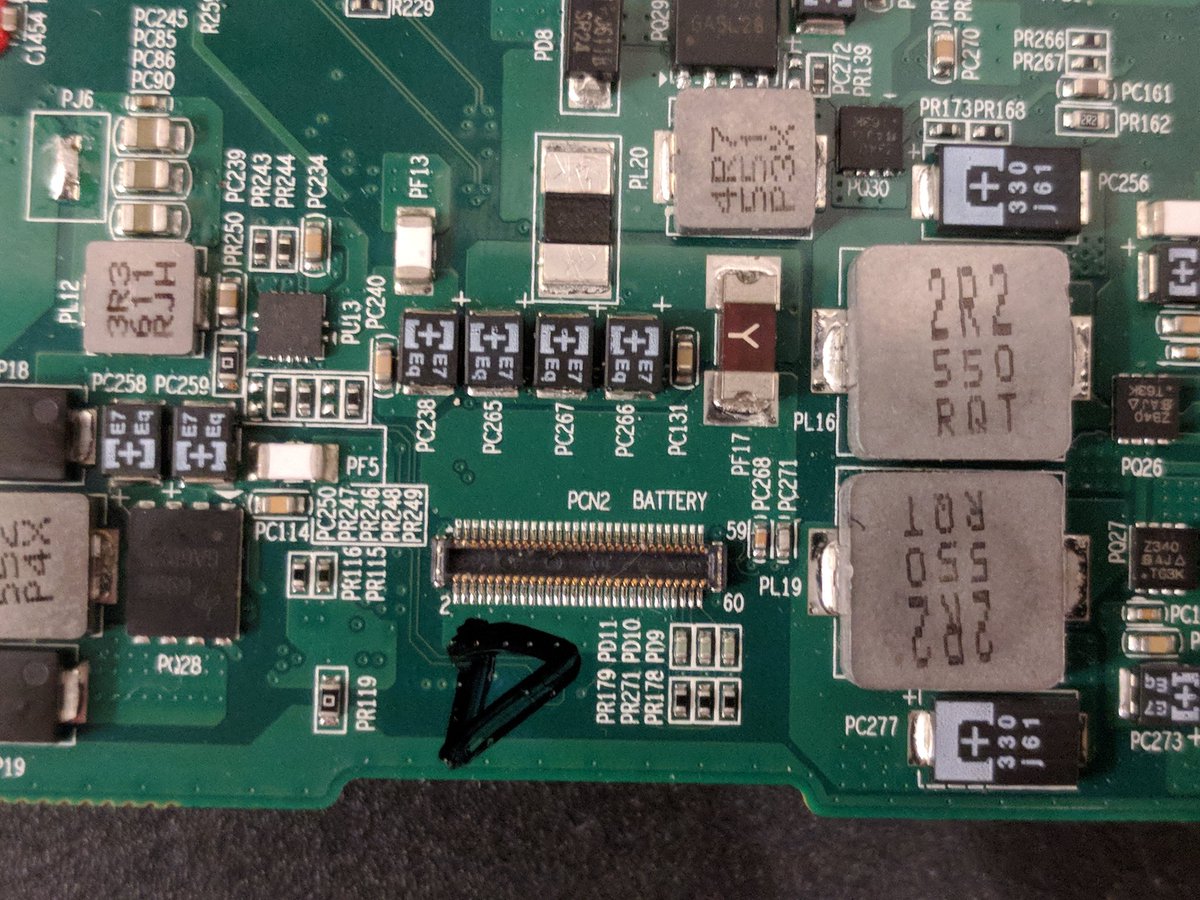
Mmmk so, first thing I'm going to do is remove this fuse with the y label to make sure there aren't any vias to other parts of the board Im missing, then this will become the start of my chain. I'll mount some more permanent pins on there after that.

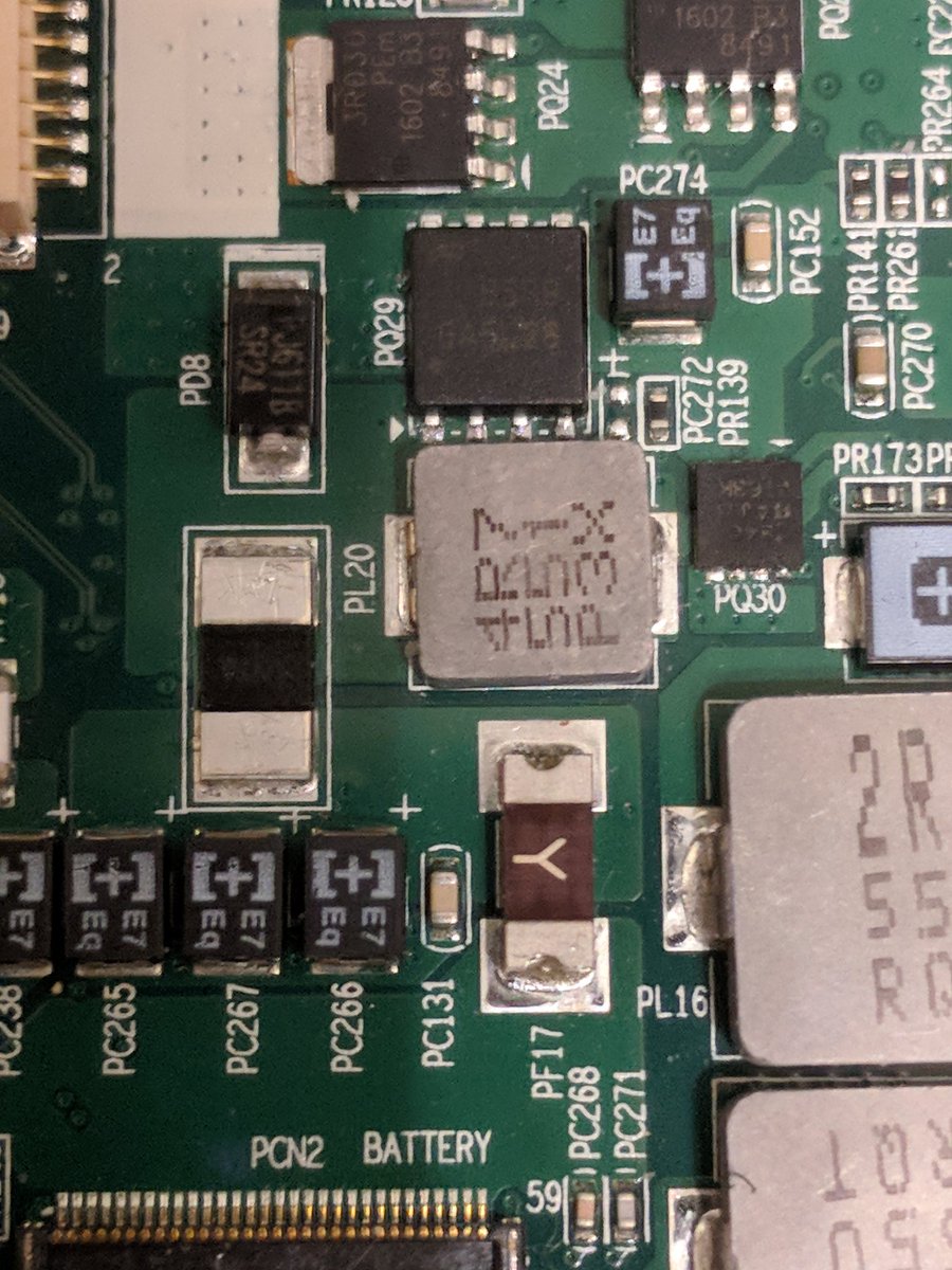
God I hate non-lead solder. Shouldn't need to break out the hot-air station to deflow a fuse. Anyway yeah start of chain is good and here's the ugliest debug pin mount of all time. Im tempted to just wait for the FLIR to show up on Tuesday before I continue :/

Next step will be determining the next isolation point methinks. I'm thinking maybe the battery charger IC is burnt, meaning multiple paths can cause fatal current draw. I can either try isolating downstream or maybe removing the battery ic.
So, at this point I gotta just work my way down the board pulling fuses. Each fuse looks to be for a separate subsystem, meaning I'm going to need to pull them for each individual subsystem. First, potentially better plan, may be to go after all those jumper points instead.
Here's a bunch of the fuses, I took a lot of pics so I could get them all mapped out. Any spot with those white smd devices labeled with "PF" followed by a number is a fuse.


Actually scratch that I need to be at work early tomorrow, so instead I'm going to go crash, and I guess tmrw night I'll go after all these fuses? I'm not excited about this part.
Gonna list suspicions I have about the failed part, though:
Gonna list suspicions I have about the failed part, though:
All the parts I think are likely candidates are parts which are in direct connection with the main power line and are powered even when the system is off.
That narrows the search field to any of the IC's used for initial bringup + 1 outlier.
That narrows the search field to any of the IC's used for initial bringup + 1 outlier.
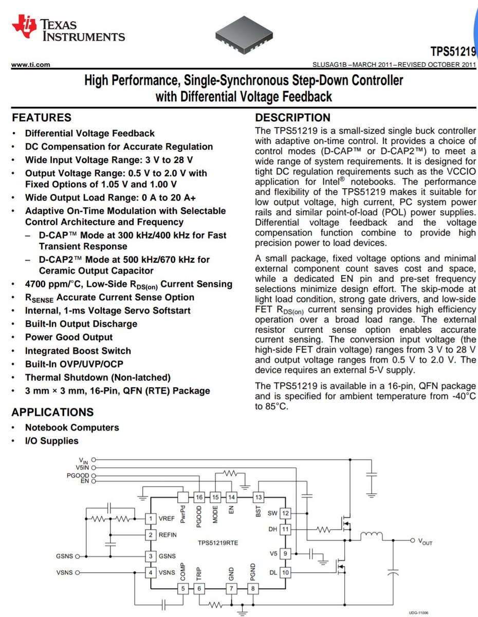
Platform controllers/bringup: we have a set of DC/DC converter controllers etc here.
Pic 1, Each of the qfn chips controls a set of FETs which generate the 5V and 20V rails.
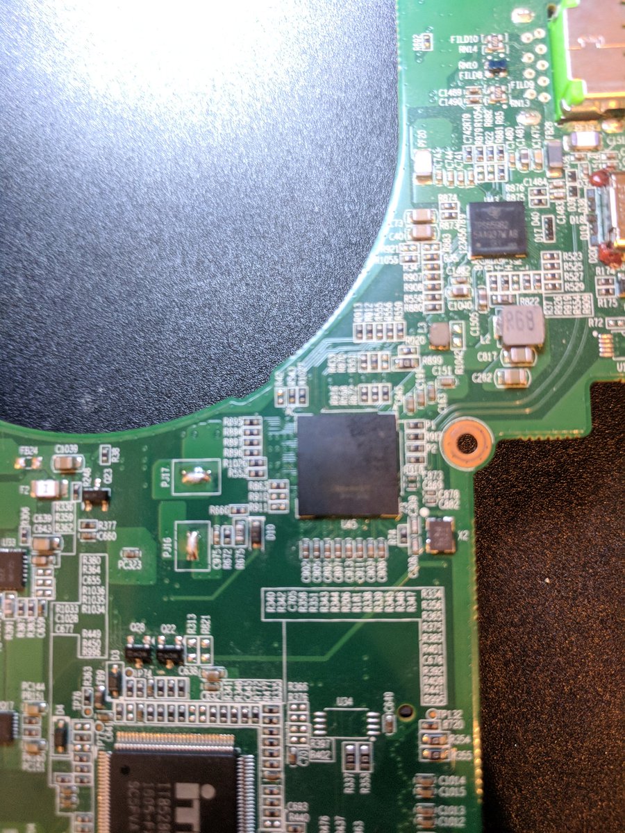
Pic 2, the main CPU supply controller? Think it drives the on/off button?
Pic 3: platform controller...
Pic 1, Each of the qfn chips controls a set of FETs which generate the 5V and 20V rails.
Pic 2, the main CPU supply controller? Think it drives the on/off button?
Pic 3: platform controller...


...which afaict is a set of different power state functionality controls tied to a basic MCU with low sleep-state power draw, which likely kicks the rest of the computer into gear. Idk, I haven't poked at a PC's guts like this before.
Also of potential interest:
Pic 1 is just a birds-eye
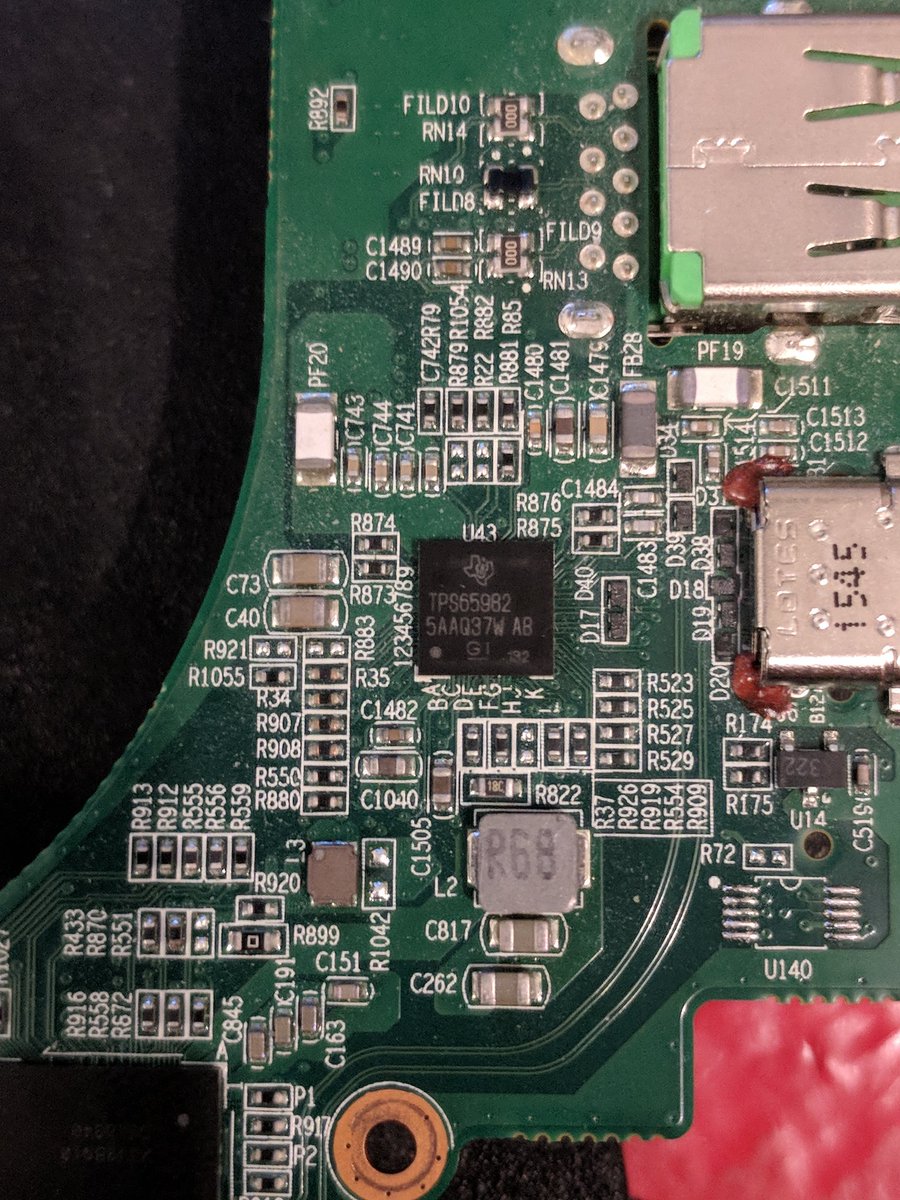
Pic 2 is, I believe, a usb-pd/USB-C controller, likely similar to the one @whitequark was (is?) fighting with. This laptop can charge USB-C devices while off, so its powered somehow.
Pic 3: I have no idea. Anyone know?
Pic 1 is just a birds-eye
Pic 2 is, I believe, a usb-pd/USB-C controller, likely similar to the one @whitequark was (is?) fighting with. This laptop can charge USB-C devices while off, so its powered somehow.
Pic 3: I have no idea. Anyone know?
Anyway that's all of the likely candidates for this failure I can identify. It's likely one of them or one of their surrounding passives that failed, so now the question is which, and what fuses isolate each of these subsystems.
Anyway I'll pick this back up tmrw night after work, with any luck I'll be able to isolate the faulty point tmrw, or if not then the flir shows up on Tuesday and I'll give that a shot. See you all tomorrow, and sleep well!
So, let's get to it!!
Step 1. Set max voltage with open leads
Step 2. Set max current with closed leads
Step 2. Set max current with closed leads


Step 3: hook up
Step 4: power on! (Only don't turn on this supply while it's connected because I don't trust this supply to power on cleanly so I attached gnd, then turned on, then attached Vdd)
Step 4: power on! (Only don't turn on this supply while it's connected because I don't trust this supply to power on cleanly so I attached gnd, then turned on, then attached Vdd)


Didn't work, not enough heat to get picked up by the IR sensor, which is curious. I havs some ideas and also some pics from the flir but I'mma save those for tmrw cuz I need to pass out
Whoa look at that! Found the short it's in the GPU it must be getting so hot!!!
Except that the board isn't powered right now.
This is a good time to talk about infrared-band light, and why infrared cameras work.
Except that the board isn't powered right now.
This is a good time to talk about infrared-band light, and why infrared cameras work.


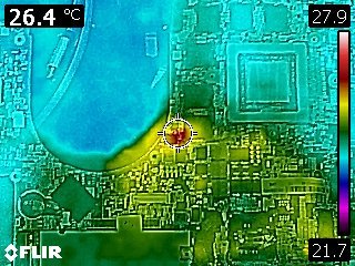
So, here's another image demonstrating the issue:
This is the back of the board. Look at the non-IR image. The "heat" is in the shape of the heatsink mounting backplane. Why? Well, there's a lot to explain, but the easy hand-wave is that metal is reflective to infrared.
This is the back of the board. Look at the non-IR image. The "heat" is in the shape of the heatsink mounting backplane. Why? Well, there's a lot to explain, but the easy hand-wave is that metal is reflective to infrared.


In addition, glassy surfaces are too. Here's proof:
That's a selfie, taken in a mirror. The mirror doesn't have a heat pool in the shape of me, that's IR light reflected in the mirror, and I'm the "source"
That's a selfie, taken in a mirror. The mirror doesn't have a heat pool in the shape of me, that's IR light reflected in the mirror, and I'm the "source"

Basically, all things "give off" infrared light. When atoms vibrate thanks to heat, they create disturbances the same way that electrons hopping around do, but they're at a much lower frequency. This is what we mean when we talk about heat transfer "by radiation"
Its a concept called "black body radiation" and it's complicated, but basically if the device is cooling, it's shedding heat, and if it's shedding heat it's radiating some of that energy as IR. That's the easiest way to explain it.
The thing is, all materials handle heat differently. Some emit more IR than others, and some materials are reflective and don't absorb the energy they're hit with, they reflect it instead. Metals are IR reflective. To an IR camera, they appear hotter than stuff around them.
So, these metal parts throw off the measurement, making this difficult. However, I have an idea. I'll post pics in a few minutes, I really hope this works.
(feel like I should tag @bofh453 since they're the other physics nerd I can think of off the top of my head, and my blackbody theory isn't excellent so it's totally possible I'm completely talking out my ass and they can correct me in that case)
It worked!!
Basically, I needed to coat the IR reflective surfaces with something that was semi-glossy but also thermally insulating like the PCB. Good thing, I have one such material and it's already sticky: kapton tape!
Basically, I needed to coat the IR reflective surfaces with something that was semi-glossy but also thermally insulating like the PCB. Good thing, I have one such material and it's already sticky: kapton tape!

Ok, now to coat all the inductors and major points of exposed metal (the inductors have shown themselves to be pretty thermally conductive too)
(ps @fouroctets don't steal my thunder!!)
All taped up, bois. Now I get to do the fun part: get things hot and hope it works.
Ok now /this/ may actually be something. 200 mW of power approximately (200 mA, <1 V), and it may be defusing through the backside. I should tape up the other side too, but I'll leave that for the weekend.

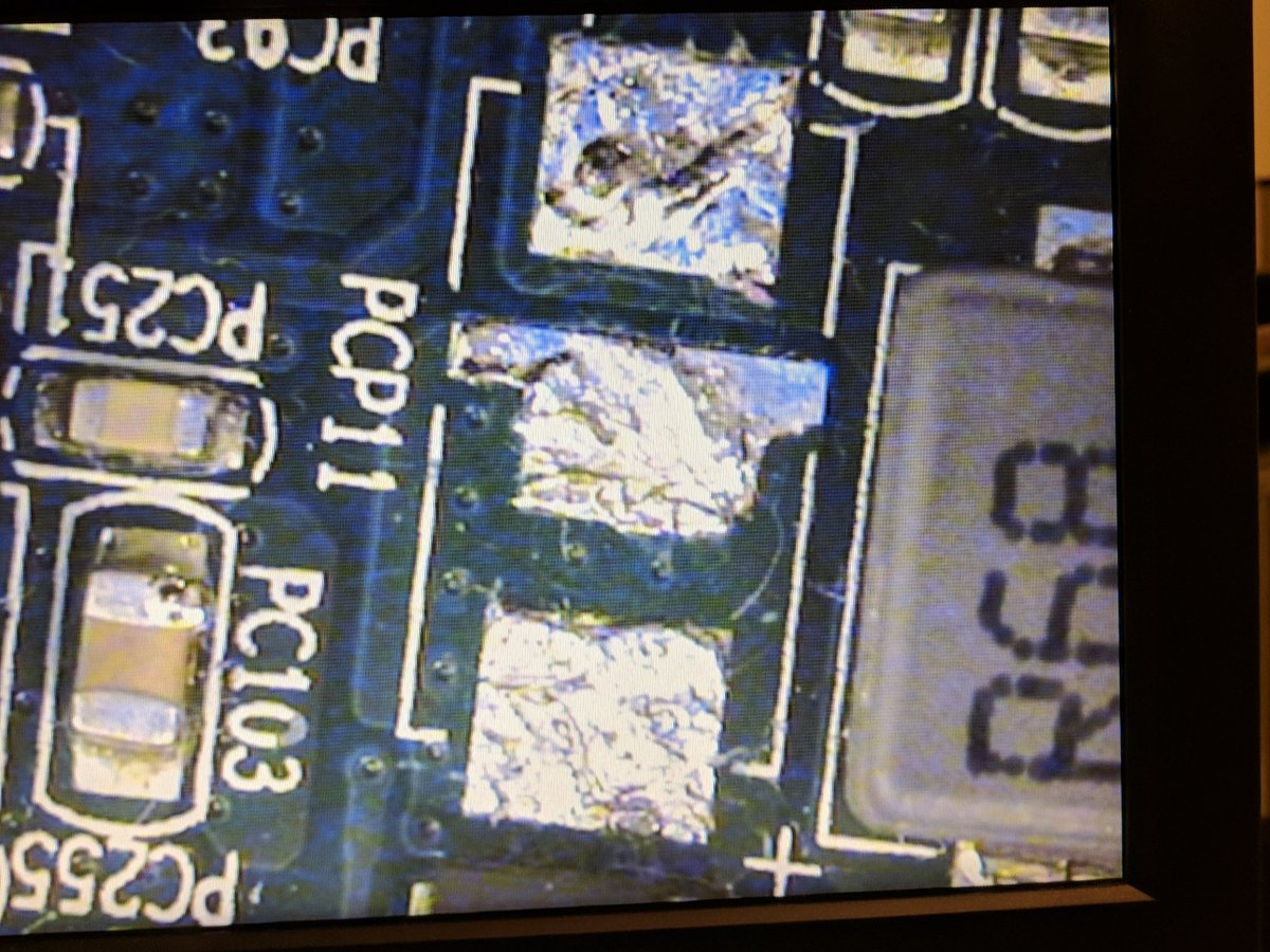
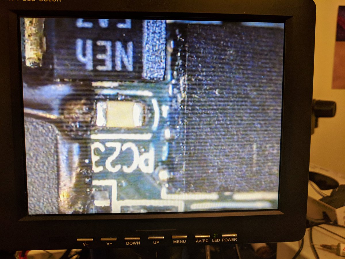
Scratch that, flipped over the board and immediately noticed something was off. One of the IC's right under that heat patch? I went and inspected and it looked weird, so I poked it a bit and look at what came off. I'mma put this under the scope.


Lol I don't think that's what that's supposed to look like


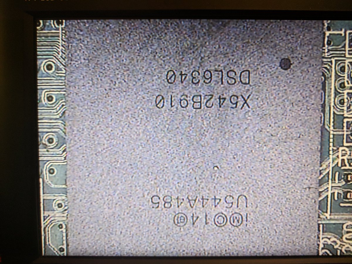
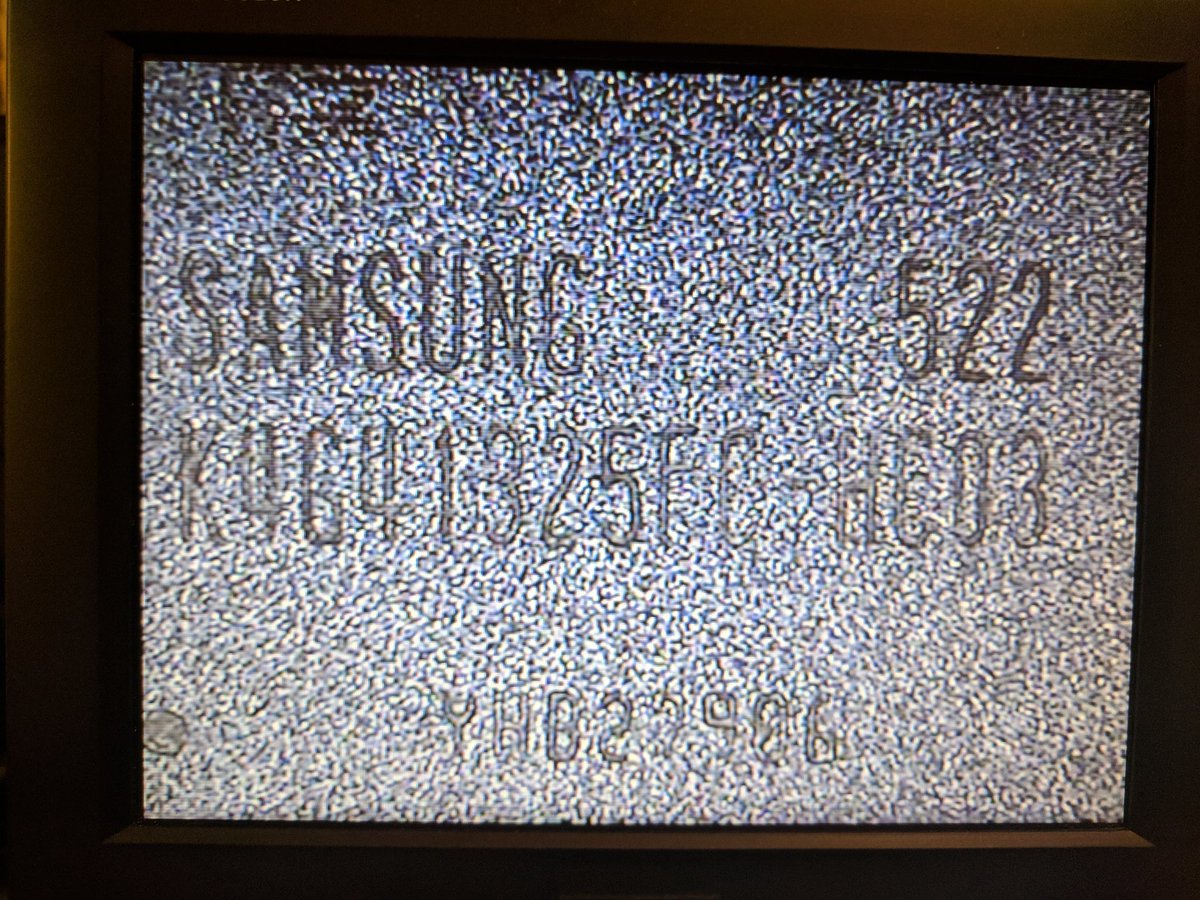
Cleaned it off to get the part number, and yeah that makes a lot of sense. Long story short, the power supply system was the culprit if I'm right, now I need to remove and replace this ic. Good news is if this is the problem it's a common component. Keep them fingers crossed!

Anyway guys that was productive and I'm going to sleep I think. I'll poke at removing/testing tmrw, and we'll just have to hope I didn't kill anything while debugging!
So, I wanna see what the heat profile looks from the top of the board, so I went ahead and got the tape going on this side too. I'll do the test after I make some spaghetti!
So, went ahead and tested again, this time on the side with the heat source and most of the heat is coming from... The electrolytic cap? (Because of the sensor, the IR is shifted up a bit from the regular optical image). Second image is IR profile without any power.

The cap shows 3 ohms across it. Yeah I think that's a cascade failure: burnt ic = burnt cap? Question is if the other caps are also burnt. One way to find out I guess: do the repair, and see if it's fixed or not afterwards? Either way, it's time to pull the bad IC and the cap.


So I got the components off the board, took forever to flow off. Here's the board without the components tho, with some mediocre cleanup.
In addition, lost one smt cap and one smt res, and I'll need to figure that out. Now I have to move to testing.
In addition, lost one smt cap and one smt res, and I'll need to figure that out. Now I have to move to testing.


Also, while I was working I dropped my tweezers and this happened, which uh... Hey at least I know my tweezers are still sharp??


Oh and if you thought I'd do reflow without taking IR pics then I'd call you a damn fool! Check this shit out.
Also, this would have been impossible without a rework station. It is an absolutely essential tool to this kind of maintenance.
Also, this would have been impossible without a rework station. It is an absolutely essential tool to this kind of maintenance.


It's holding a voltage!!!!! Guys it's holding a voltage and not seeing a short!!!!
It goes through a 3-second-or-so cycle of drawing 40 mA or so and then drops to 2 mA!!!! Guys it did an initial-boot cycle!!!!
It goes through a 3-second-or-so cycle of drawing 40 mA or so and then drops to 2 mA!!!! Guys it did an initial-boot cycle!!!!


Power is getting delivered to the power button... And I can press it which triggers a big increase in current draw... everything else is working... I cannot explain how good I feel right now.

Ok I need to order the replacement parts and figure out if I can supply a dummy voltage past that buck regulator IC to test the things downstream too, but I think that may be a fan controller actually.
That's for tomorrow. For tonight I'm going to go be happy and relax.
That's for tomorrow. For tonight I'm going to go be happy and relax.
So, ordering components now. After this, all that I can do until the parts show up is test past the damaged supply.
The faulty supply was the low-voltage supply to GDDR5 (part shown below), so I can make sure the GPU DRAM chips are functional still by applying the desired voltage and checking the current. If (chip * desired_current) = (measured_current), I'm in the clear!
The thing is that this failure could totally have caused a cascade failure that blew out the GPU DRAM, and if that's the case then I'd need to replace all 10 probably. That's a hell of an undertaking since all the chips are epoxied on and are bga.
So, I guess I should test that, pray that current looks about right, and then move on to the work I have to do for my actual job until the parts show up, but worst case I could just completely disable the discrete GFX portion for now? Not huge on that, but it's doable.
Ok let's get back to it! Hopefully I can wrap this up today!


So, first I'm cleaning up the pads using the better wick I bought with my order. QFN footprint is wicked with new wick and not ipa rinsed, the cap footrpint was with the old wick. Imo difference is clear.

Picture doesn't really do it justice, but imo it's way better

Got something on my iron tip that melted and now I need to take a few minutes to let my office vent
Mmk, applied new solder to pads, cleaned, and now I'll apply new flux before putting the parts back on!


Ok, all fluxed up, parts are down, time to get this party started!


Here we go!!!!

Ok, parts are on! I need to do some touch-up on the buck controller with my microsoldering tip, the contacts on the cap are unconnected too so that needs to be fixed, and I gotta get that missing resistor on, and then it's testing time!


Hmm, didn't work. Had to re-remove the components to verify that it's still functioning. Figuring some stuff out here though, I think the real failure may actually be that the supply drive mosfet may be dead. If thats the case, most of the GDDR5 is dead too.
As far as I can tell, the MOSFET has failed short, and is refusing to cut off the supply, which is the source of all the other failures. Replacing the components worked mostly, but too much power was still supplied to the end node.
If I got really lucky, then the electrolytic cap acted as a fuse and blew out before the DDR5 did. At this point, I think the best plan is just to test and replace the inductor, diode, and fet in the buck converter and see which is really dead.
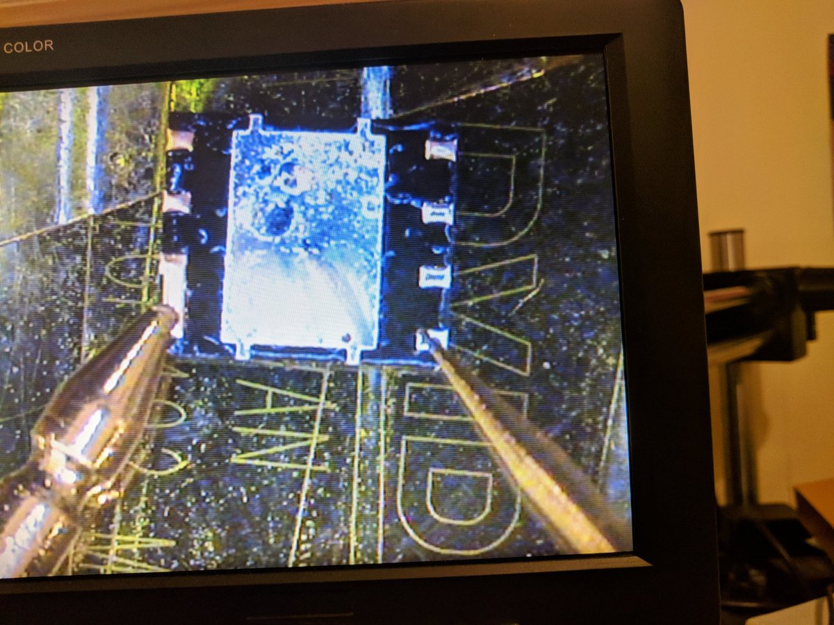
Here's the "FET", turns out it's 2 FETs + driver. Assuming this is default powered (i.e. it's not staged and gets a direct vdd supply), if this is shorting vcc to vout then it is also definitely faulty. I'm going to remove this IC, probe pads, and then re-attach the others.

On one hand, I'm frustrated that the cascade failure apparently killed 3 or 4 parts, but on the other hand I'm hopeful that the cascade failure was instant enough to protect the RAM. Let's fire up the hot air station again and pull this chip, then probe.
And there you have it, yup that's definitely a short. Ok so, I'm going to go ahead and order the replacement from wherever I can with overnight shipping (so maybe arrow?)


Tmrw when I have a chance I'll flip the 2 replacement components I do have back onto the mobo and confirm those work as much as possible without the driver. It's progress, regardless of how slow.
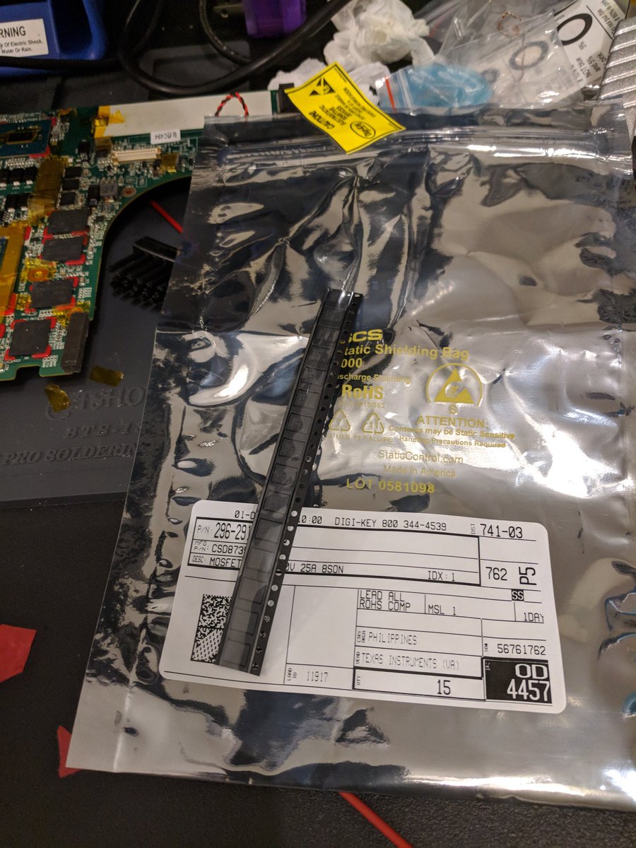
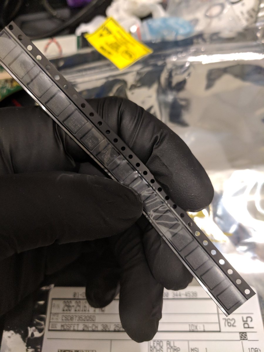
Ok the new FET's showed up! Let's get back to work!
Also, I'm wearing gloves this time because I've been worried about lead contact, I'll prolly shed them early on if they make my soldering bad.
Also, I'm wearing gloves this time because I've been worried about lead contact, I'll prolly shed them early on if they make my soldering bad.

Cleaned up the pads, then applied paste by hand, kinda doubt this will work but we'll see what happens!


Went ahead and cleaned the pads, then applied some old paste by hand. This could go badly, or could be great.


That went... Surprisingly well??? I might need to use paste more often for large things? If anything I put too much but it worked out well. Time to test connections and then do current-limited power test.


So, the connections look good. Ngl I'm anxious as hell. It's time to give this a test but first quick review. Here's a bird's eye view of the work region.
For added context, components in order they were replaced:
1️⃣ Buck controller
2️⃣ Load cap
3️⃣ Buck driver fet pair
For added context, components in order they were replaced:
1️⃣ Buck controller
2️⃣ Load cap
3️⃣ Buck driver fet pair


Guys it's not delivering too much power in the off-but-powered state anymore. The main supply is stable. I think it's working...
Ok, this is something. Maybe the issue is that I'm not cooling it and the CPU is detecting an overheat trend, or maybe some other component is failing, but either way it's getting far enough to start the platform controller. Worst case, I should have platform controller uart now.
I think I'm going to go ahead and apply the heatsink rig and see if that changes the behavior, worst comes to worst I'll have to clean the CPU's off again, could be worse.
Look i should cut off the end of this because I legitimately almost started crying and I feel like a weirdo but I'm in too good of a mood
YES! THAT IS RIGHT I DID IT!
NUMBER 5 ARE YOU KIDDING ME???
WHO DO YOU THINK YOU ARE???? I AM!!!!!!!!!
NUMBER 5 ARE YOU KIDDING ME???
WHO DO YOU THINK YOU ARE???? I AM!!!!!!!!!