,
27 tweets,
12 min read
Read on Twitter
The last couple of weeks, I've been working on a new hardware iteration of Wobble Garden. Here's a little thread on Wobble Garden so far and my thought- & production-process for the next version! ⬇️ 

After the initial prototypes, this will be the third version using printed circuit boards. The first one was just a Line Wobbler strip zig-zagged around some springs on wood:
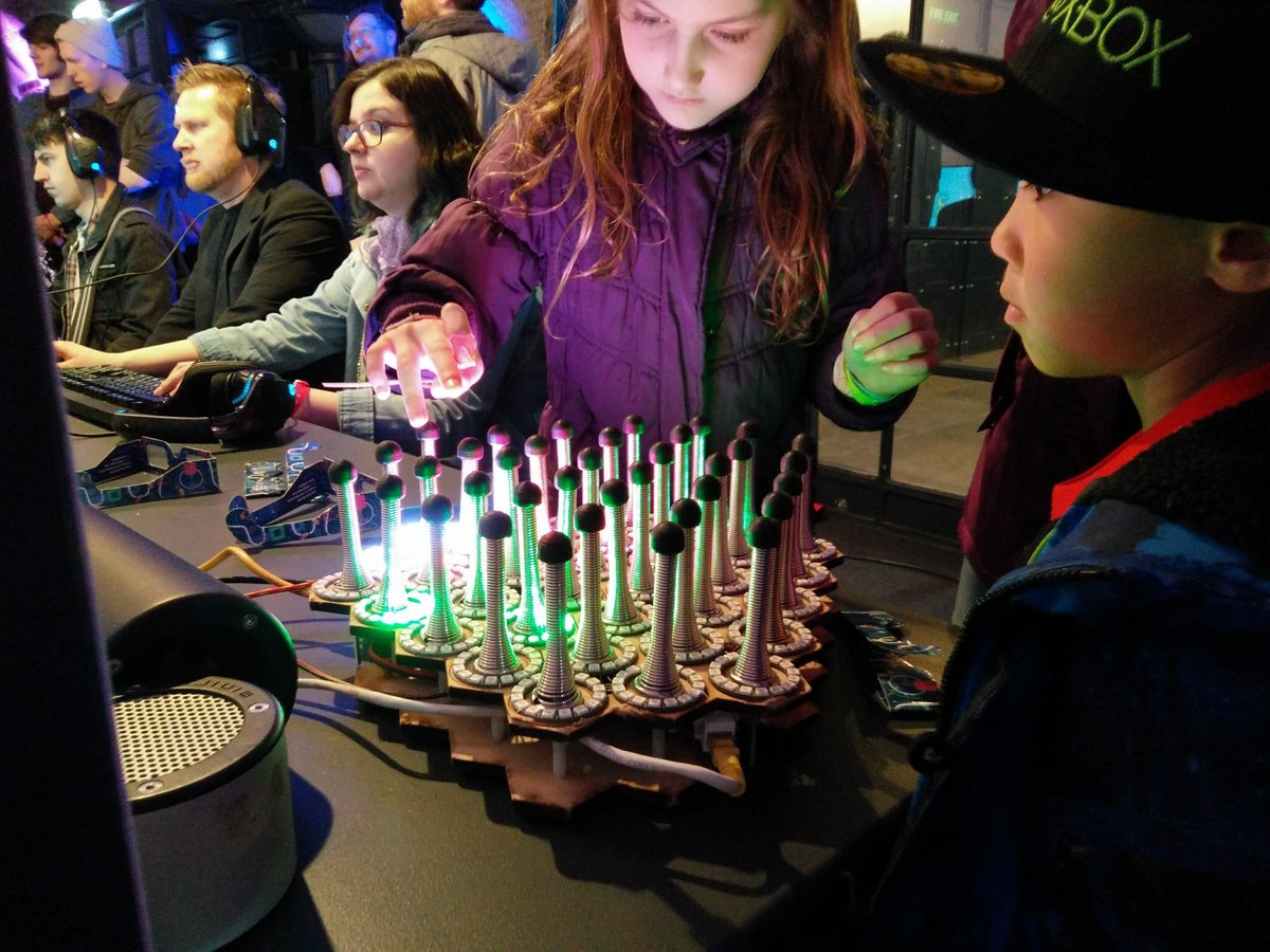
Since that looked good, I built the next version with rings in a hex grid. Current WGs still have the same layout:
In these versions the LED rings were all individually hand-soldered, quite a pain! That meant there was quite a bit of wiring (aka Kabelsalat) going on, leading to a sandwich design. This version has been quite sturdy actually though!


Since there was enough interest in the installation, I looked into automating some of the building process. Having everything on printed circuit boards was one thing I looked into. That meant figuring out a way to tile hexagon patterns!


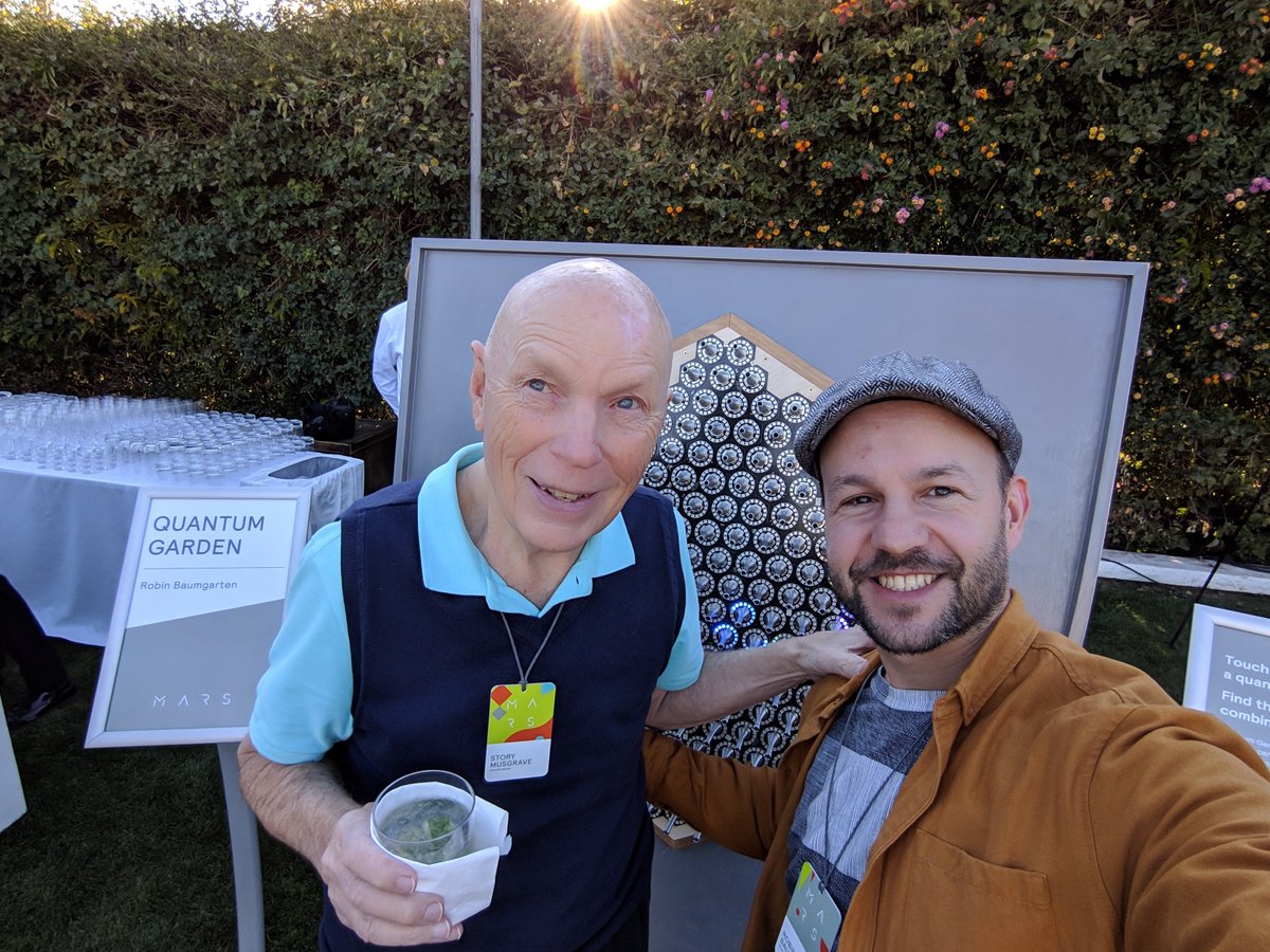
I ended up with this shape. The touch sensors I use have 12 channels, so it made sense to put 12 springs on a board. 19 of these would make up the shape for the large Wobble Garden, that I then used in the Quantum Garden installation for Aalto University:

This is the first circuit board design! You can see the four large pads that the springs would sit on to transmit the capacitive touch data to the sensor on the underside. There's also space for a Teensy Arduino there, and lots of dupont connectors.


First problem: The springs would scratch through the PCB coat and ground themselves, which meant they'd stop working as touch pins:

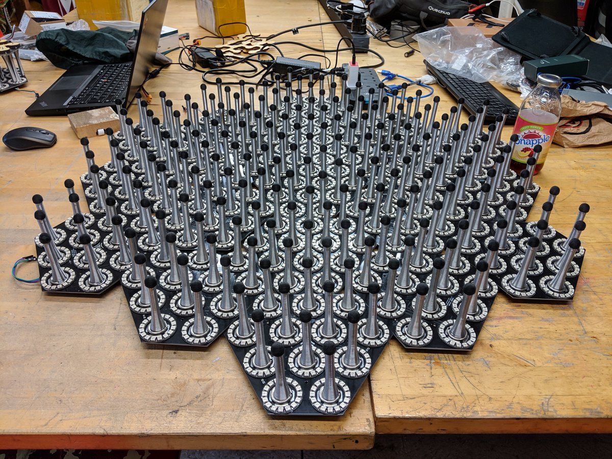
Still, with very careful screwing it'd work, and that meant I had the first PCB based (small) Wobble Garden, made up of 48 springs and one Arduino:

It worked pretty well! I used 3D printed conductive caps for the springs then (but have ditched them now since they'd break too often and were a pain to print).
Time to build larger versions! "Quantum Garden" was commissioned by Aalto University & the Turku Quantum Computing Group as an interactive installation to showcase quantum computing algorithms in a citizen science context.


It had some minor PCB issues as well, but overall it worked really well! It got a lot of attention on reddit and twitter, too, which led to more opportunities to show it. ☺️
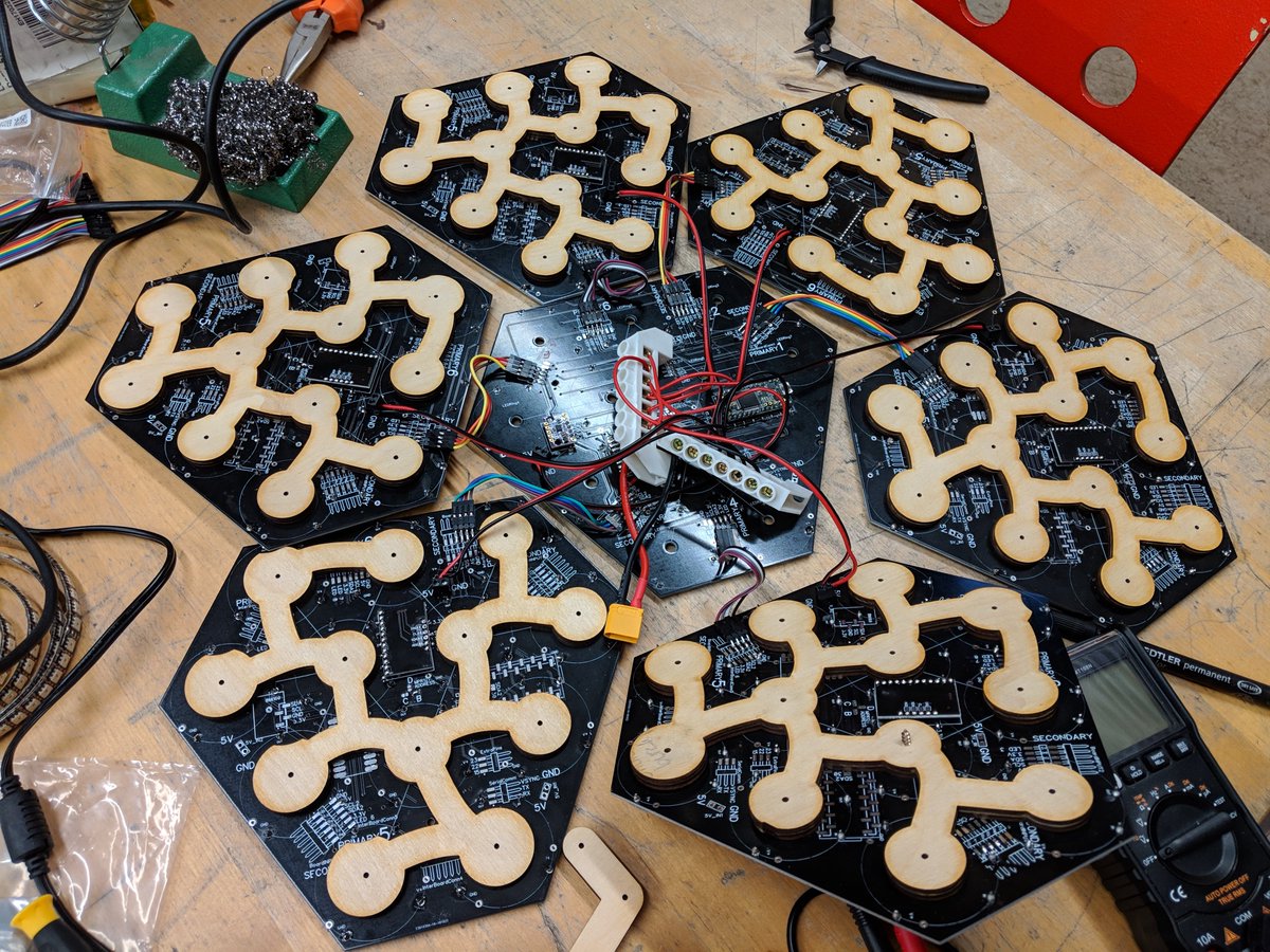
The next step was to reduce the wiring mess (I hate cables!). So after a weekend browsing the weird and wonderful world of connectors and PCB accessories, I found these neat board-to-board connectors:


These new connectors worked quite well, and surprisingly fit really well first try:


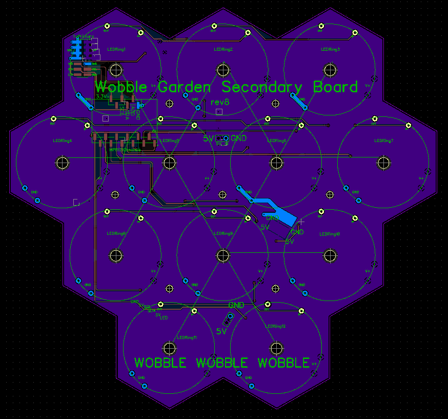
So far, there's two different PCBs in here, those with the Teensy on them (called Primary boards) and ones without (Secondary boards). This cut down on wiring drastically, I just needed to feed power to this, and one usb cord per Teensy:

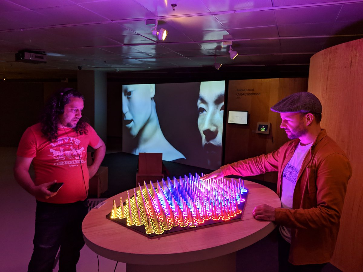
I've shown this design at a few places now, at one I had a real-life astronaut play it, and the other was in a cool Quantum Computing & Cybernetic Consciousness exhibition in Sao Paulo!
This worked well enough, but this design is super-hard to maintain: if you want to swap out one PCB (because LEDs are broken or something), you'd have to unscrew all 12 springs, and then try to pry it off the board-to-board connector, which sandwiches the board in place.

And also, since there's two different PCBs (with and without Arduinos on them), it's difficult to trouble-shoot and get spares.

Sooo! This brings us to the last few weeks. I decided to make a 'control board' that sits below the LED boards, so that:
- all LED boards are the same and without much logic
- the LED boards can be hot-swapped easily with 3 screws
- the Logic boards are small & also swappable.
- all LED boards are the same and without much logic
- the LED boards can be hot-swapped easily with 3 screws
- the Logic boards are small & also swappable.
This is a side-view of how it's going to look, with some variants on how some of the parts are mounted. I'm going to use header pin connectors for power & data (blue), with most of the LED logic & teensys sitting on the board below.

This is how the LED board looks like in the PCB design software (I'm using @DipTrace). As you can see, there's not too many parts. The connector is in the top left, next to the capacitive touch sensor (an MPR121).
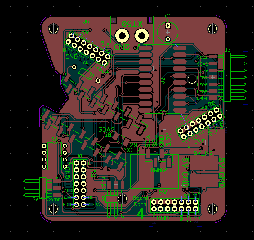
The control board is a bit busier:
There's 4 connectors that connect to the LED boards, the Teensy arduino, a level shifter, a dip switch (for telling the Teensy where it is in a larger installation) and some connectors for expansion boards.
There's 4 connectors that connect to the LED boards, the Teensy arduino, a level shifter, a dip switch (for telling the Teensy where it is in a larger installation) and some connectors for expansion boards.
Trying to figure out how these connectors would line up was an excellent little puzzle, and took me a few days of fiddling around to get right(ish). I mostly used Inkscape to play around with and align the shapes (the connectors are in red below):

I've also been re-thinking the shape of the LED PCBs while I was at it and figured out that a 2x6 configuration like this is maybe better for tiling larger installations:

That makes the control board shapes simpler, and hopefully easier to connect. This is how those PCBs will look like (except they'll be matte-black). You can also write anything you want on them, I should add some jokes somewhere! :D

To 'test' if the layout will align properly, I export everything as pdf and overlay it in inkscape, resulting in this mess:

Anyway, that's where I am right now, waiting for my PCBs to be printed by JLCPCB. It's quite exciting to see the little prototypes make their way through the steps in real-time (nice!). I'll update this when the boards arrive next week! 👨🔬🤪